OpenAir™ GLB Enhanced Non-Spring Return Rotary Electronic Damper Actuator Technical Instructions
Document Number 155-785
January 20, 2017
Siemens Industry, Inc. Page 11
WARNING:
All six outputs of the dual auxiliary switch (A and B) must only be connected to:
Class 2 voltage (UL/CSA).
Separated Extra-Low Voltage (SELV) or Protective Extra Low Voltage
(PELV) (according to HD384-4-41) for installations requiring conformance.
WARNING:
Installations requiring Conformance:
All wiring for CE certified actuators must be SELV or PELV rated per
HD384-4-41.
Use safety-isolating transformers (Class III transformer) per EN61558.
They must be rated for 100% duty cycle.
Over current protection for supply lines is maximum 10A.
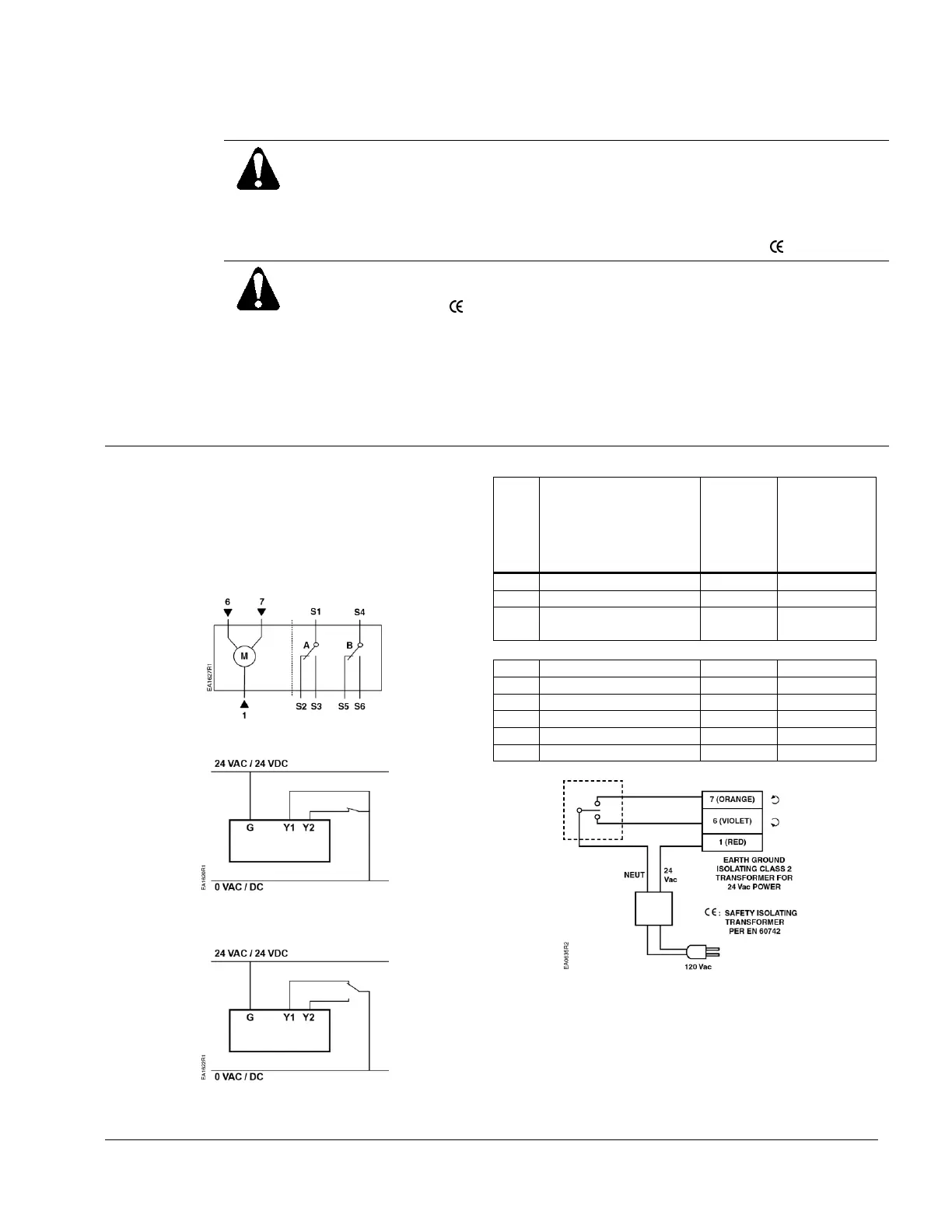
Wiring
Each wire has the standard symbol printed on it. See
Table 3.
GLB14x
24 Vac/dc Power Supply, 2-Position/Floating
Control
Figure 18. GLB14x Wiring Diagram.
Figure 19. 2-Position, SPST
(Single-Pole, Single-Throw).
Figure 20. 2-Position, SPDT
(Single-Pole, Double-Throw).
Table 3. 2-Position/Floating Control 24 Vac/dc.
Control signal
counterclockwise
Factory-installed Options
Figure 21. Floating Control, 24 Vac/dc.

 Loading...