Technical Instructions OpenAir™ GLB Enhanced Non-Spring Return Rotary Electronic Damper Actuator
Document Number 155-785
January 20, 2017
Page 12 Siemens Industry, Inc.
Wiring, Continued
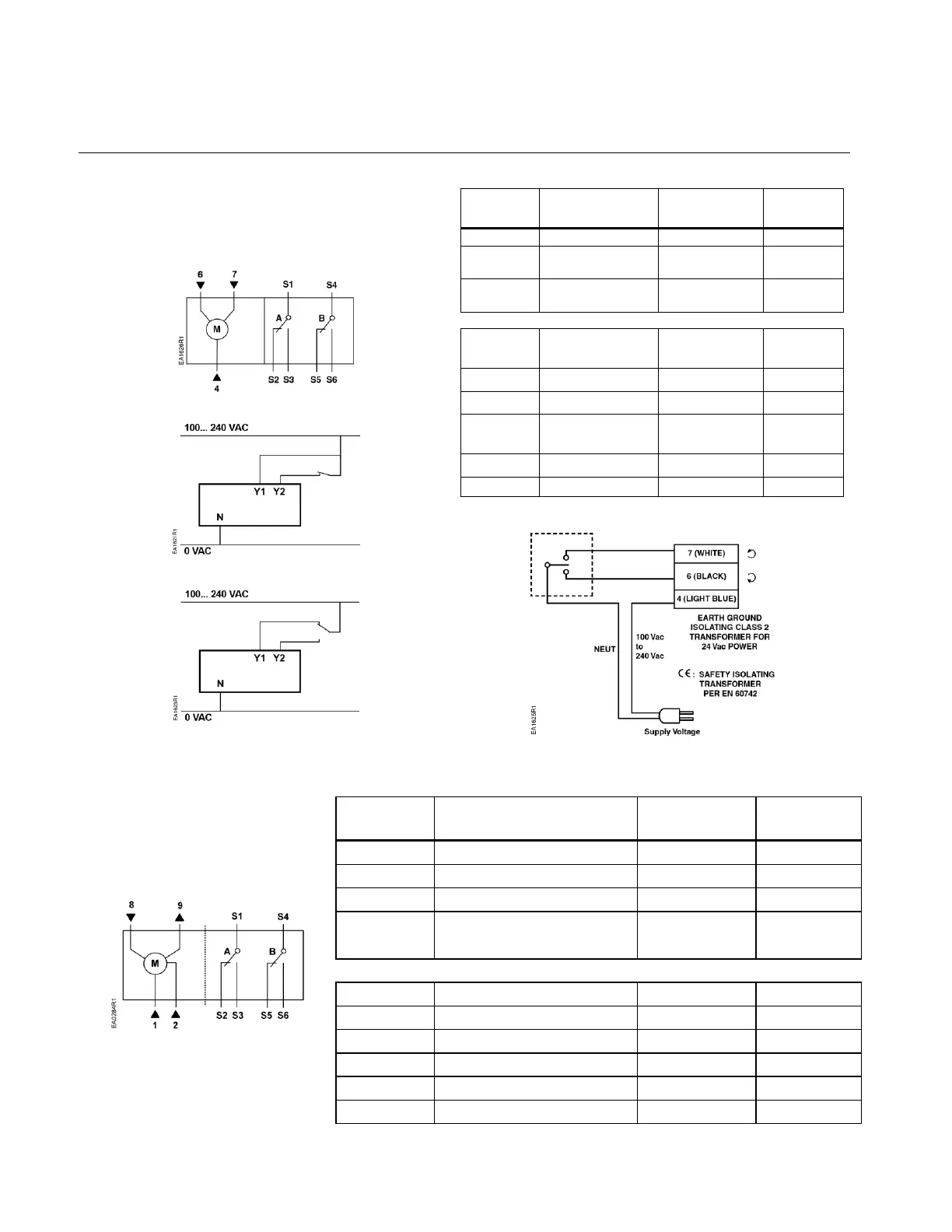
GLB34x
100 to 240 Vac Power Supply, Two-Position
Floating Control
Each wire has the standard symbol printed on it. See
Table 4.
Figure 22. GLB34x Wiring.
Figure 23. 2-Position, SPST
(Single-Pole, Single-Throw).
Figure 24. 2-Position, SPDT
(Single-Pole, Double-Throw).
Table 4. Two-Position, Floating Control, 100 to 240 Vac.
Control signal
counterclockwise
Factory-installed Options
Figure 25. Floating Control, 100 to 240 Vac.
Table 5. Modulating Control, 24 Vac/dc.
GLB 16x
24 Vac/dc Power Supply, 0(2)
to 10V Modulating Control
Figure 26. GLB16x Wiring.
0(2) to 10 Vdc input signal
Output for 0(2) to 10 Vdc
position indication
Factory-installed Options

 Loading...