40
PAD-4
Operation, Installation, and Maintenance Manual
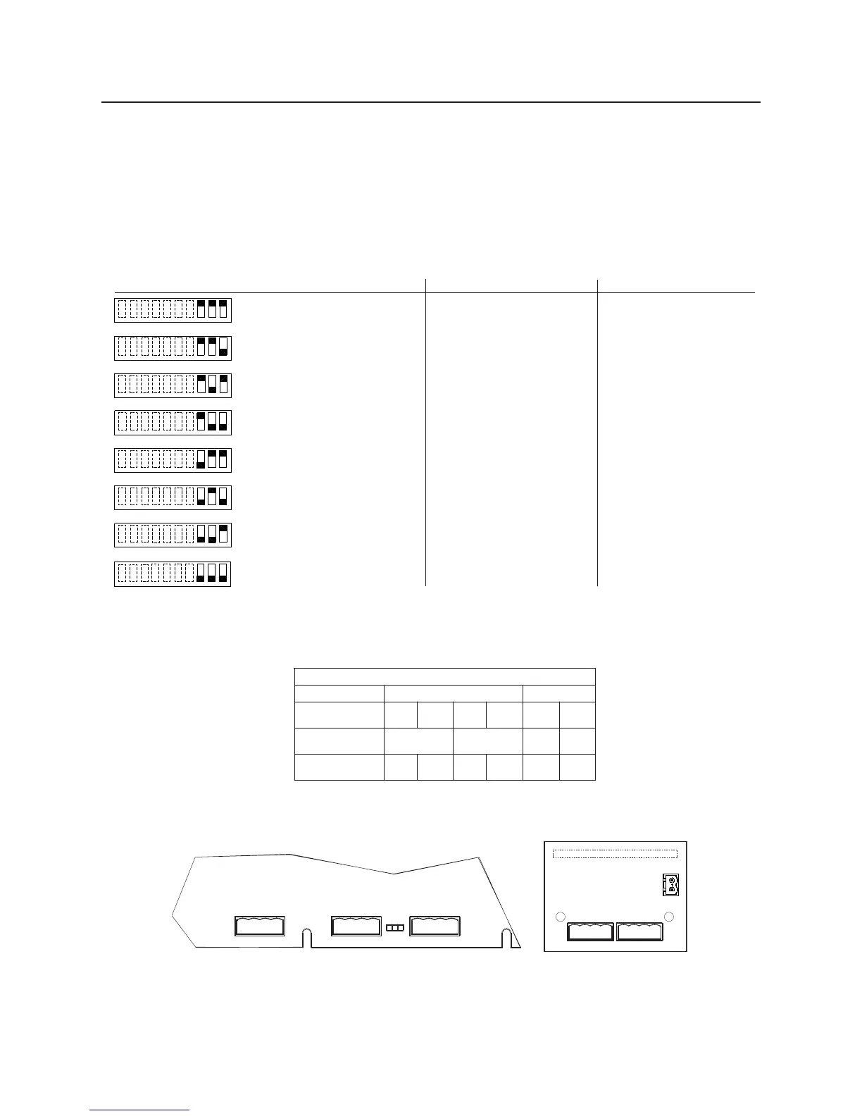
5.1.1 Selecting the Input/Output Configuration
Figure 5-1 shows the position of each switch on the DIP switch for various input and output configura-
tions. Refer also to Figure 5-2 for the terminal block designated on the PAD-4 or PAD-4-CLSA board.
The position of switch 4 through 10 does not affect the relationship of inputs to outputs.
Note: Changing settings for DIP switches 1-3 may affect the settings for jumpers J4-J8.
ON
OFF
Switch 1 OFF & Switch 2 OFF & Switch 3 OFF:
Input 1 controls outputs 1B - 4B (Class B).
Input 2 not used.
Switch 1 ON & Switch 2 OFF & Switch 3 OFF:
Input 1 controls outputs (Class B).
Input 2 used to control silencing of Sync horns.
1B-4B
Switch1OFF&Switch2ON&Switch3OFF:
Input 1 controls outputs 1B, 2B and 3B (Class B).
Input 2 controls output 4B (Class B).
Switch1ON&Switch2ON&Switch3OFF:
Input 1 controls outputs 1B and 2B (Class B).
Input 2 controls outputs 3B and 4B (Class B).
Switch 1 OFF & Switch 2 OFF & Switch 3 ON:
Input 1 controls outputs 1A and 2A as Class A.
Input 2 not used.
Switch1ON&Switch2OFF&Switch3ON:
Input 1 controls outputs as Class A.
Input 2 used to control silencing of Sync horns.
1A and 2A
Switch 1 & Switch 2 ON & Switch 3 ON:
Input 1 controls outputs 1A as Class A.
Input 2
OFF
controls outputs 2A as Class A.
Not Applicable
NO PAD-4-CLSA BOARD
UL INSTALLATION ONLY
WITH PAD-4-CLSA BOARD
UL INSTALLATION ONLY
Switch1ON&Switch2ON&Switch3ON:
Input 1 controls outputs 1A, 2A and 3A (Class A).
Input 2 controls output 4A (Class A).
Not Applicable
Not Applicable
Not Applicable
Not Applicable
Switch1OFF&Switch2OFF&Switch3ON:
Input 1 controls outputs 1A - 4A as Class A.
Input 2 not used.
Switch1ON&Switch2OFF&Switch3ON:
Input 1 controls outputs as Class A.
Input 2 used to control silencing of Sync horns.
1A - 4A
Switch 1 & Switch 2 ON & Switch 3 ON:
Input 1 controls outputs 1A and 2A as Class A.
Input 2
OFF
controls outputs 3A and 4A as Class A.
WITH PAD-4-CLSA BOARD
ULC INSTALLATION ONLY
Switch1ON&Switch2ON&Switch3ON:
Input 1 controls outputs 1A, 2A and 3A (Class A).
Input 2 controls output 4A (Class A).
Switch 1 OFF & Switch 2 OFF & Switch 3 ON:
Input 1 controls outputs 1A - 4A as Class A.
Input 2 not used.
Switch1ON&Switch2OFF&Switch3ON:
Input 1 controls outputs as Class A.
Input 2 used to control silencing of Sync horns.
1A - 4A
Switch 1 & Switch 2 ON & Switch 3 ON:
Input 1 controls outputs 1A and 2A as Class A.
Input 2
OFF
controls outputs 3A and 4A as Class A.
Switch 1 OFF & Switch 2 OFF & Switch 3 OFF:
Input 1 controls outputs 1B - 4B (Class B).
Input 2 not used.
Switch 1 ON & Switch 2 OFF & Switch 3 OFF:
Input 1 controls outputs (Class B).
Input 2 used to control silencing of Sync horns.
1B-4B
Switch1OFF&Switch2ON&Switch3OFF:
Input 1 controls outputs 1B, 2B and 3B (Class B).
Input 2 controls output 4B (Class B).
Switch 1 ON & Switch 2 ON & Switch 3 OFF:
Input 1 controls outputs 1B and 2B (Class B).
Input 2 controls outputs 3B and 4B (Class B).
910 8 76 54321
910 876 54321
910 876 54321
910 876 54321
910 876 54321
910 876 54321
910 876 54321
910 876 54321
TB14
TB15
NAC3B
NAC4B [NAC2A]
_
+
_
+
NAC1B
NAC2B [NAC1A]
_
+
_
+
1
1 1
TB16
J8
AUX PWR SUPPLY
_
+
NAC4A
_
+
_
+
NAC3A
_
+
_
+
TB1
TB2
PAD-CLSA
1
1
P1
PAD-4 PCB
TB3
GND
FLT
NO
COM
1
2
3-1SEHCTIWSPID1SGNIMMARGORP
BCP4-DAPASLC-4-DAP
noitangiseDlanimreT
BCPno
B1CANB2CANB3CANB4CANA3CANA4CAN
noitarugifnoCAssalC
noitangiseD
A1A2A3A4
noitarugifnoCBssalC
noitangiseD
B1B2B3B4A/NA/N
Figure 5-1
Setting DIP Switches 1-3
Figure 5-2
Designation of NAC Outputs on PAD-4 PCB and PAD-4-CLSA
 Loading...