41
PAD-4 Operation, Installation, and Maintenance Manual
5.1.2 Setting the Auxiliary Output
Switch 4 on the DIP switch determines how the
auxiliary power operates.
The PAD-4 checks switch 4 only when powering
up. If you change this switch, you must push
switch S2 momentarily to reset the unit to recog-
nize the new switch setting.
Switch 4 OFF:
Auxiliary Power Output always on.
65432
ON
OFF
65432
ON
OFF
Switch 4 ON:
Auxiliary Power Output will shutdown
30 seconds after an AC Power Fail
and the unit is running on battery.
Figure 5-3
Setting DIP Switch 4
5.1.3 Setting the Input’s NAC Control
DIP switch settings 5 to 8 are designed to pro-
duce outputs from a constant on input. The
figures shown below compare the output patterns
of configurations before and after the addition of
this feature.
Slave Operation
The Slave operation output follows the input and
can be used when the fire alarm control unit NAC
is steady, coded, march time, or temporal and
the desired output is the same.
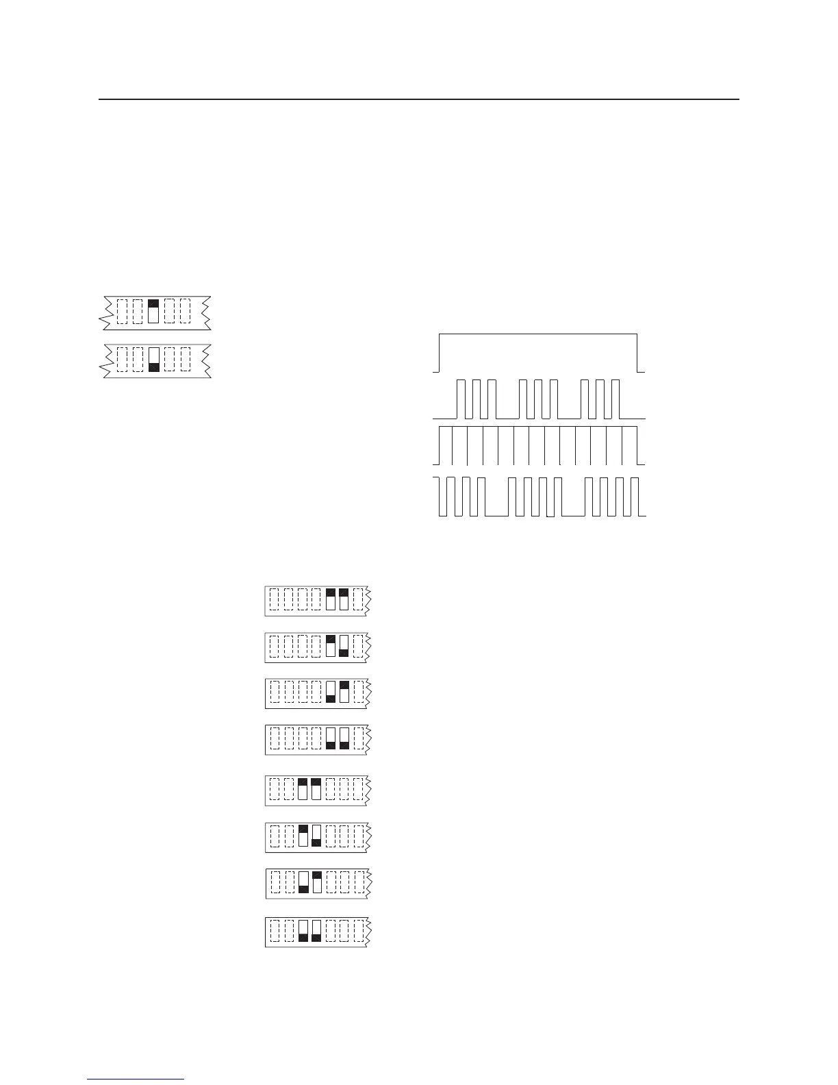
Master Temporal Operation
Master Sync Strobe/Horn Operation
Master Carbon Monoxide (CO) Alarm Operation
Input:
Steady
Output:
Temporal
Operation
Output:
Sync Strobe/
Horn Operation
Output:
Carbon Monoxide
(CO) Alarm
Figure 5-4
Master Input/Output Relationship
910 8 76 54
ON
OFF
Switch 5 OFF & Switch 6 OFF:
Slave Operation-Input 1’s outputs will follow the input
pattern (steady in, coded, march time, temporal, or Sync).
Switch 5 ON & Switch 6 OFF:
Master Temporal Operation-Input 1’s outputs will be
temporal when the input is on steady.
Switch 5 OFF & Switch 6 ON:
Master Sync Strobe/Horn Operation-Input 1’s outputs will
provide Sync signals when the input is on steady.
Switch 7 OFF & Switch 8 OFF:
Slave Operation-Input 2’s outputs will follow the input
pattern (steady, coded, march time, temporal, or Sync).
Switch 7 ON & Switch 8 OFF:
Master Temporal Operation-Input 2’s outputs will be
temporal when the input is on steady.
Switch 7 OFF & Switch 8 ON:
Master Sync Strobe/Horn Operation-Input 2’s outputs will
provide Sync signals when the input is on steady.
910 8 76 54
910 8 76 54
910 8 76 54
910 8 76 54
910 8 76 54
Switch 5 ON & Switch 6 ON:
CO Configuration-Input 1’s outputs will provide CO alarm
when the input is on steady.
910 8 76 54
Switch 7 ON & Switch 8 ON:
CO Configuration-Input 2’s outputs will provide CO alarm
when the input is on steady.
910 8 76 54
Figure 5-5
Setting DIP Switches 5-8

 Loading...