Table of Contents
1 PAD-5 ................................................................................................................... 5
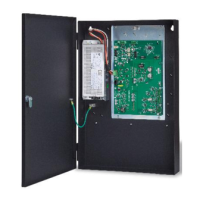
1.1 Description ............................................................................................................ 5
1.2 Properties ............................................................................................................. 6
1.3 Regulatory Standards ........................................................................................... 8
1.4 General Specifications.......................................................................................... 8
2 Installation ........................................................................................................... 9
2.1 Mounting the Boards .......................................................................................... 12
2.2 DPU programming PAD-5-MB and expansion card address ............................. 13
2.3 Wire Routing ....................................................................................................... 14
3 Wiring the PAD-5 .............................................................................................. 16
3.1 AC Wiring ........................................................................................................... 16
3.2 Wiring and Configuring the PAD-5-MB ............................................................... 17
3.2.1 Wiring Power Supply and Battery to the Main Unit ............................. 19
3.2.1.1 Battery Compatibility ...................................................................................... 20
3.2.1.2 X101 Battery terminal .................................................................................... 21
3.2.2 NAC Circuits ....................................................................................... 22
3.2.2.1 Wiring the NAC circuits – Class B NAC1 and NAC2 (NAC1 ......................... 23
Class A) and Class B NAC3 and NAC4 (NAC2 Class A) ............................................... 23
3.2.2.2 NACs (1-4) Configured as Auxiliary Circuits .................................................. 25
3.2.2.3 NACs (1-4) Configured as Shorting Device Inputs......................................... 25
3.2.2.4 NAC Follower Input ........................................................................................ 26
3.2.2.5 Wiring X600 NAC Follower Terminal Block ................................................... 26
3.2.2.6 X600 NAC Follower ...................................................................................... 28
3.2.3 Dedicated Auxiliary Output (X800) ..................................................... 28
3.2.3.1 Wiring the Dedicated Auxiliary Output ........................................................... 28
3.2.3.2 X800 Auxiliary output terminal block .............................................................. 29
3.2.4 FDNet (P2) Wiring and Topologies ..................................................... 29
3.2.4.1 Wiring X700 FDNet (P2) Input ....................................................................... 29
3.2.4.2 X700 FDNet (P2) terminal block .................................................................... 29
3.2.4.3 Topologies ..................................................................................................... 30
3.2.5 LED Indicators ..................................................................................... 33
3.2.6 Switches .............................................................................................. 34
3.2.6.1 S600 Main Board RESET .............................................................................. 34
3.2.6.2 S601 Reset Status LED switch ...................................................................... 34
3.2.6.3 S602 Ground Fault Supervision Switch ......................................................... 34
3.3 Technical Data .................................................................................................... 34
3.4 Battery Size Calculations ................................................................................... 36
4 Battery Maintenance ........................................................................................ 38
 Loading...