Do you have a question about the Siemens PAD-5-CLSA and is the answer not in the manual?
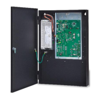
The PAD-5-CLSA is an add-on card for the PAD-5 Main Board, providing four additional NAC circuits.
Details the characteristics of the four power limited NAC outputs, configuration options, and integrated circuitry.
Lists the PCB assembly and hardware kit components included with the expansion board.
Step-by-step instructions for physically installing the expansion board, including screw and standoff placement.
Guidelines for separating high voltage and power limited wiring to prevent noise and ensure proper operation.
Identifies key components and their locations on the PAD-5-CLSA board for wiring and configuration.
Details wiring for Class A/B NACs, auxiliary outputs, and shorting device inputs.
Explains the function of switches S600, S601 and the disconnect switch for controlling releasing circuits.
Illustrates the wiring diagram for Class B releasing circuits, including REL-EOL and solenoids.
Shows the wiring diagram for Class A releasing circuits, including notes on loop wire termination.
Explains that NACs 5-8 synchronize like NACs 1-4, managed via the Zeus programming tool.
Details the meaning of various LED indicators and the functions of associated switches for configuration and control.
Provides detailed specifications for supply input, NAC circuits, releasing circuits, and auxiliary outputs.
| Brand | Siemens |
|---|---|
| Model | PAD-5-CLSA |
| Category | Computer Hardware |
| Language | English |