Model PAD-5-CLSA
1
Properties
7
Siemens Industry, Inc.
A6V101030359_en--_c
Building Technologies Division
2 Installation
PAD-5-CLSA
SCREWS
QTY = 2
STANDOFF
QTY = 2
MALE FEMALE
STANDOFF
QTY = 1
SCREW “A”
DAUGHTER
BYPASS
BOARD
LOCATION
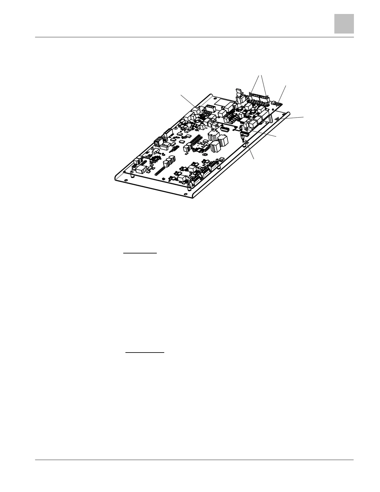
Figure 2: Typical Configuration
Parts Supplied:
1. PCB Assembly inside the antistatic bag.
2. Hardware kit inside the polybag.
Kit includes:
a) (2) standoffs 4-40 x 13/16” long
b) (1) standoff male-female ¼” hex, 5/16” long, 6-32 thread
c) (2) screws 4-40 x ¼” long
d) (2) terminal blocks 4 position
e) (1) installation instructions
f) (4) 24K 1/2W Carbon Film EOL Resistors, P/N 140-034677
MOUNTING THE BOARD
1. Remove the daughter bypass board that is factory installed on X901 (location
shown in Figure 2), before attaching the expansion board to the PAD-5-MB.
2. Remove the mounting screw (screw “A”) next to expansion connector X900
(do not discard) the screw will be reused.
3. Attach the two 13/16” standoffs provided, unto the backbox as shown on
Figure 2.
4. Attach the male-female standoff to the PAD-5-MB as shown in Figure 2.
5. Plug in the board as shown in Figure 2. Align the two connectors from the
PAD-5-CLSA with the two connectors on the main board.
6. Use the two 13/16” screws provided to secure the board in place.
7. Attach screw “A” to the PAD-5-CLSA board and the male-female standoff as
shown in Figure 2.
 Loading...