Installing/Mounting
3.2 Dimensions and drill pattern
Power Module PM240
28 Hardware Installation Manual, 07/2009, A5E00807525B AD
PPರ
PPರ
PPರ
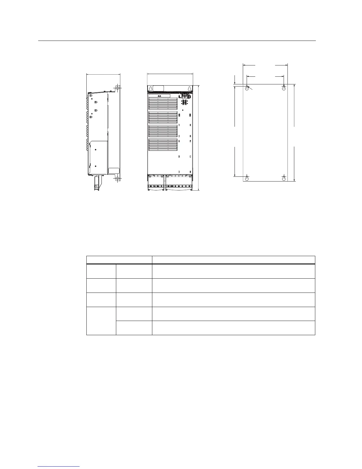
)RUIL[LQJ
[0EROWV
[0QXWV
[0ZDVKHUV
7LJKWHQLQJWRUTXH1P
OEILQ
+HLJKWLQFRPELQDWLRQZLWKWKHVFUHHQ
WHUPLQDWLRQNLWZR%UDNH5HOD\
PPLQFK
PP
PP
PP
PP
PP
PP
Figure 3-8 Dimensions and drill pattern, FSE filtered (HO 30 kW ... 37 kW)
Table 3- 9 Minimum distances for mounting
Minimum distances FSE Note
side by
side
0 mm
0 inches
above 300 mm
11.81 inches
below 300 mm
11.81 inches
40 mm
1.57 inches
Additional distance to the front with Control Unit CU240E front
65 mm
2.56 inches
Additional distance to the front with Control Units CU240S,
CU240S DP, CU240S PN, CU240S DP-F and CU240S PN-F