Do you have a question about the Siemens PM240 and is the answer not in the manual?
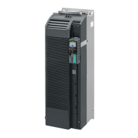
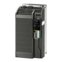
Introduces the SINAMICS G120 inverter system comprising Control Unit and Power Module.
Lists types of PM240 Power Modules with braking capacity and defines power rating values.
Illustrates block diagrams for PM240 Power Modules (FSA-FSF and FSGX) showing component interconnections.
Lists available technical documentation, internet addresses, and application examples.
Provides general warnings, cautions, and notes for safety and preventing equipment damage.
Covers warnings on voltages, qualified personnel, earthing, isolation, and static discharge for safe operation.
Details safety for electrical installation, cable connections, mechanical installation, and general operation precautions.
Outlines safety procedures for equipment repair, dismantling, and disposal.
Provides general rules for safe installation, environmental conditions, and mounting orientation.
Details airflow requirements, calculation methods, and avoidance of air short circuits for proper cooling.
Shows dimension drawings and minimum mounting distances for FSA frame size.
Provides dimension drawings and minimum mounting distances for FSB frame size.
Displays dimension drawings and minimum mounting distances for FSC frame size.
Shows dimension drawings and minimum mounting distances for FSD frame sizes.
Displays dimension drawings and minimum mounting distances for FSE frame sizes.
Shows dimension drawings and minimum mounting distances for FSF frame sizes.
Shows dimension drawings and minimum mounting distances for FSGX frame size.
Describes how to fit the Control Unit to different Power Module frame sizes (FSA-FSF and FSGX).
Covers safety for electrical connections, power distribution systems, and IT supply operation.
Provides guidelines on motor cable length, cross-section, grounding, and terminal access.
Details DC 24V power supply, fan voltage adjustment, and line contactor control for FSGX modules.
Offers guidelines and methods for avoiding EMI and ensuring proper screening during installation.
Outlines maintenance tasks including dust removal, ventilation checks, and terminal inspection.
Details procedures for replacing cooling fans, fuses, relays, power blocks, and control interface modules.
Lists key performance ratings like operating voltage, frequency, overload capability, and braking options.
Explains operating temperature and altitude derating for output current and input voltage.
Provides comprehensive technical data for Power Modules across different frame sizes and power ratings.
Describes the functions and installation of reactors and filters (line, output, sine-wave) for Power Modules.
Details the function, installation, connection, and protection of brake choppers and braking resistors.
Covers brake relay types, mounting, connection, and DIN rail/screen termination kits.
Explains EMC compliance, environments, categories, emissions, immunity, and relevant standards.
Lists standards the product complies with and provides a glossary of abbreviations used in the manual.
| Protection Class | IP20 |
|---|---|
| Frame Size | FSA to FSF |
| Number of Phases at Input | 3 |
| Number of Phases at Output | 3 |
| Altitude | Up to 1000 m above sea level without derating |
| Input Voltage | 380-480 V 3 AC |
| Output Frequency | 0 Hz |
| Communication Interfaces | USS, Modbus RTU, PROFIBUS |
| Efficiency | Up to 98% |
| Cooling Method | Forced air cooling |
| Operating Temperature | -10°C |
| Storage Temperature | -40 to +70 °C |
| Relative Humidity | 5 to 95 % non-condensing |
| Control Type | V/f control |