Device description
3.2 6ES7972-0BA30-0XA0
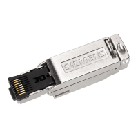
PROFIBUS bus connector
Equipment Manual, 02/2021, A5E50543113-AA
13
Mounting the bus cable
1. Strip the insulation from the bus cable as shown in Fig. 1.
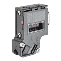
2. Open the casing of the bus connector by undoing the screws ➁
and removing the cover.
3. Press the bus cable into the strain relief ➄
(cable shield must be bare on the metal guide).
4. Place the wires in the guides ➅ over the insulation displacement terminals ➃.
Ensure that the same wires are always connected to the same connection A or B
(always wire connection A with green wire and connection B
with red wire).
5. Press the red and green wires lightly into the insulation displacement terminals with your
thumb.
6. Screw the cover back on tightly.
Note
Connection of the bus l
ines
The bus lines are connected using an insulation displacement system (Fast Connect). The
insulation displacement terminals are designed for 3 connection cycles. If you want to
reconnect a line that has already been connected, you must first cut it off.
Approvals
You can find information on the approvals under Standards, approvals and safety notes
(Page 31).
Module-specific data
You can find information under Module-specific data (Page 38).