Device description
3.5 6ES7972-0Bx61-0XA0
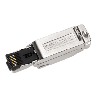
PROFIBUS bus connector
Equipment Manual, 02/2021, A5E50543113-AA
23
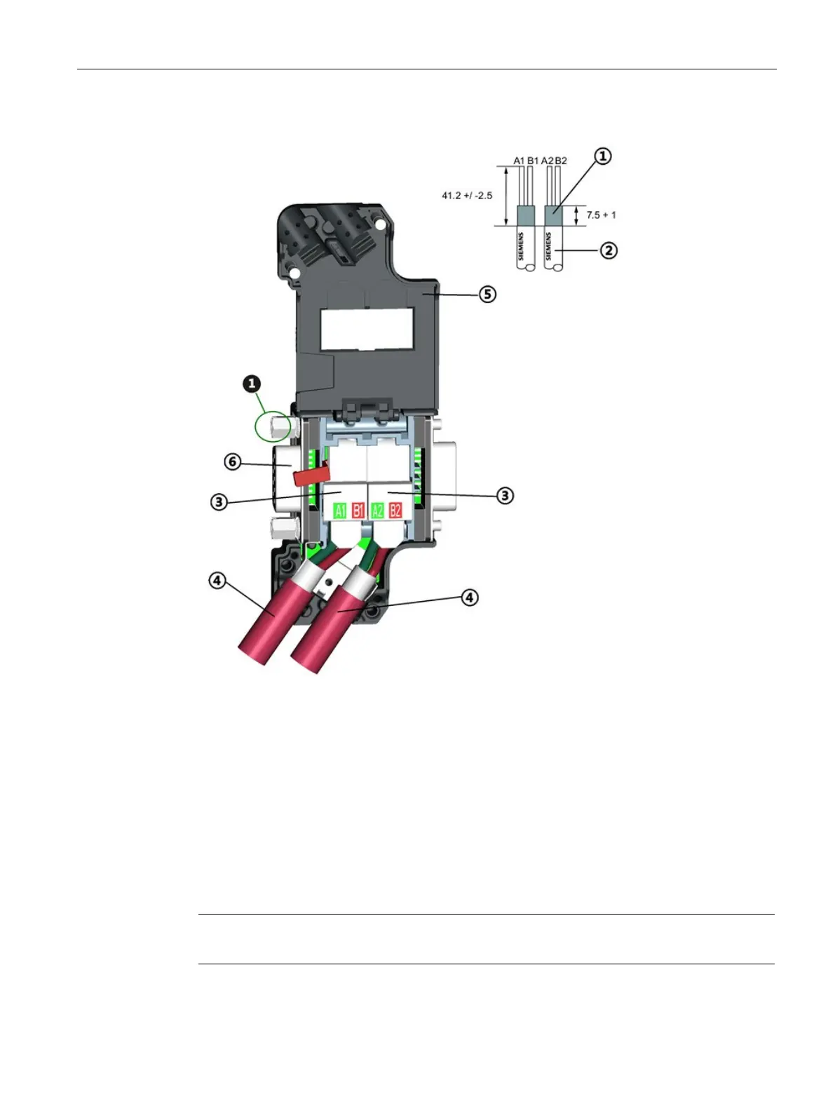
Bus cable assembly
2 Bus cable (e.g. 6XV1 830-0EH10)
- strip insulation, e.g. with stripping tool
3 Contact cover for insulation displacement terminal
- Insert the green and red wires into the open contact cover as far as they will go.
- Close the contact cover completely (press it down as far as it will go).
Press cable into recess (cable sheath must not rest on the shield plate)
Close the enclosure cover and screw it tight.
PG socket (only for 6ES7972-0BB61-0XA0)
The tightening torque of the locking screws (marked in the figure) must not exceed 0.3Nm.