Siemens Industry, Inc.
Building Technologies Division
P/N 315-033060-193
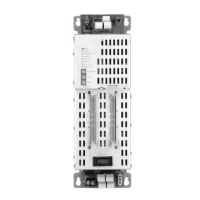
The LEDs located at the top left of the module and are
defined as follows:
POWER - (Green) Normally ON. When illumi-
nated, indicates that the PSC-12 is
powered from the AC mains. When
flashing, indicates that the PSC-12 is
powered from the battery.
MODULE FAIL - (Yellow) Normally OFF. When illumi-
nated indicates that the module micropro-
cessor has failed.
CAN FAIL - (Yellow) Normally OFF. When illumi-
nated, indicates that CAN communica-
tion with the PSC-12 has terminated
(applicable only when PSC-12 resides in
a CAN network).
HNET FAIL - (Yellow) Normally OFF. When illumi-
nated, indicates that the HNET communi-
cation with the PSC-12 has terminated and
the PSC-12 goes to degrade mode
(applicable only when the card resides in
the HNET network).
GND FAULT - (Yellow) Normally OFF. When illumi-
nated, indicates that the PSC-12 has
detected either a negative or positive
ground fault on its outputs.
24V 12A FAIL - (Yellow) Normally OFF. When illumi-
nated, indicates that the 24VDC non-
power limited output has a trouble
condition or the PSC-12 has disconnected
the 24VDC output due to current overload
or short circuit.
24V 4A FAIL - (Yellow) Normally OFF. When illumi-
nated, indicates that the 24VDC power
limited output has a trouble condition or
the PSC-12 has disconnected the 24VDC
power output due to current overload or
short circuit.
Three rotary dial switches located directly below the LEDs are used to set the HNET/
CAN network address of the PSC-12.
The terminal blocks of the PSC-12 are defined as follows (See Figures 2, 3 and 4):
TB1 Terminals 1, 2 and 3 provide connection to the FMT riser.
Terminals 4, 5 and 6 provide an output to the monitor speaker in a
remotely mounted LVM.
Terminals 7, 8 and 9 provide an input from the microphone of a remotely
mounted LVM.
Figure 2
Terminal Blocks, Controls and Indicators
NOTE:
Positive and negative ground fault detected at:
<50K ohms for TB3 terminals 1,2
<60K ohms for TB4 terminals 1,2
<40K ohms for TB1 terminals 10,11
<20K ohms for TB1 terminals 4,5,7,8
<30K ohms for TB1 terminals 1,2