Installation Instructions
Model PSR-1
Remote Power Supply
P/N 315-090911-23
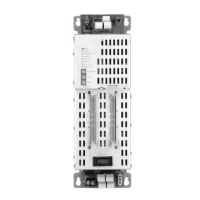
Figure 1
PSR-1 Remote Power Supply
Siemens Industry, Inc.
Building Technologies Division
Florham Park, NJ
Siemens Building Technologies, Ltd.
Fire Safety & Security Products
2 Kenview Boulevard
Brampton, Ontario
L6T 5E4 Canada
INTRODUCTION
The Model PSR-1 from Siemens Industry, Inc.,
(See Figure 1) is a microprocessor controlled
remote power supply and battery charger used
with the MXL System. It operates with an
MPS-6 or MPS-12 to provide 6 or 12 amps,
respectively, of power for various MXL mod-
ules.
In addition, the PSR-1 acts as an interface
between remote option modules and the MXL
when used with a NET-4 plug-in communica-
tion module (See Instructions P/N 315-090909)
or NET-7 plug-in communication module (See
Instructions P/N 315-091914).
The PSR-1 can also be used to power an
MOI/MOD annunciator driver set. In addition, the
PSR-1 can be used as an auxiliary power supply
in a standalone mode without an MXL.
The PSR-1 has LED status indicators for:
POWER ON, 5V AUX ON, 24V ON, BAT TRBL,
TB3 TRBL (Class A power limited output for the
CZM-1 and PS-5), GND FAULT, XMIT, ANY
TRBL, and ANY ALARM. The PSR-1 has two
relays used for common alarm and common
trouble. These relays also can be programmed
for local alarm and local trouble using CSG-M.
For additional information on the MXL/MLV
System, refer to the MXl/MXLV Manual,
P/N 315-092036.