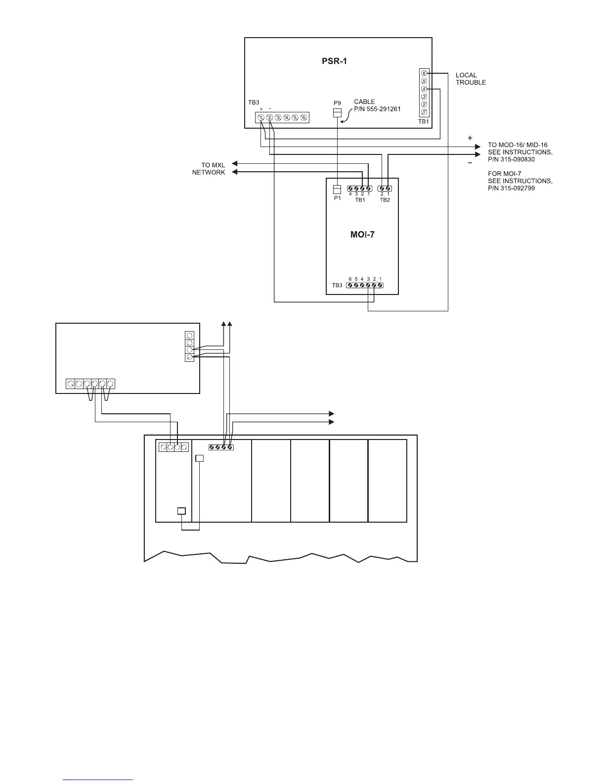
10
Figure 12
MOI-7 Connection
(in Remote Enclosure using PS-5A)
PSR-1
4
3
2
1
65
4321
23
1234
TB3
TB4
TB1
TB1
J3
P1
MOI-7 MOD-16 MOD-16 MOD-16
MID-16
PS-5A
NETWORK
NETWORK
TO MXL NETWORK
18 AWG MIN
18 AWG MIN
4 OHMS MAX
CZM-1B6 AND PS-5A POWER
SYSTEM 3 ENCLOSURE
(OR EQUIVALENT) MOUNTING
14
+
_
Figure 11
MOI-7 Connection
(in Same Enclosure)
MOM-4 Module Connection
P6 on the PSR-1 is the data and 5V connection
for the MOM-4. Connect P6 on the PSR-1 to P7
on the MOM-4 using the 8 circuit ribbon cable,
P/N 555-190506, provided with the MOM-4. A
second auxiliary non-power limited output is
provided on TB3 for the MOM-4 card cage. This
output is rated at 6 amps (MPS-6) or 12 amps
(MPS-12) 18-31 VDC. This capacity must be
derated by the current drawn by the CZM-1 and
PS-5A power output. If the full 2 amp capacity of
the CZM-1 and PS-5A output is used, the MOM-4
power must be derated to 4 amps (MPS-6) or 10
amps (MPS-12). See Figure 13 for wiring instruc-
tions.
When a PSR-1 is used with an MKB-2, use a MOM-
4 for the NET-7. Connect as shown in Figure 14.
REFER TO WIRING SPECIFICATION
FOR MXL, MXL-IQ AND MXLV
SYSTEMS, P/N 315-092772 REVISION
6 OR HIGHER, FOR ADDITIONAL
WIRING INFORMATION.
REFER TO WIRING
SPECIFICATION FOR
MXL, MXL-IQ AND
MXLV SYSTEMS,
P/N 315-092772
REVISION 6 OR
HIGHER, FOR
ADDITIONAL WIRING
INFORMATION.
POSITIVE AND NEGATIVE GROUND FAULT DETECTED AT <30K OHMS FOR TB3, 1-6
 Loading...