EasyManua.ls Logo

Siemens PSC-12 User Manual

Siemens PSC-12
12 pages
To Next Page IconTo Next Page
Page #1 background imageLoading...
Page #1 background image
Siemens Siemens
Siemens Siemens
Siemens
IndustryIndustry
IndustryIndustry
Industry
,,
,,
,
Inc. Inc.
Inc. Inc.
Inc.
Building Building
Building Building
Building
TT
TT
T
ecec
ecec
ec
hnologies Dihnologies Di
hnologies Di
visionvision
visionvision
vision
P/N 315-033060-19
12 Amp Power Supply
Installation Instructions
Model PSC-12
Figure 1
PSC-12 12 Amp Power Supply
INTRODUCTION The Model PSC-12 from Siemens Industry, Inc., is a high current power supply that
provides the FireFinder-XLS/Desigo Fire Safety Modular/Cerberus PRO Modular
system with primary regulated 24VDC. It is rated at 12A and has a built-in charger that
is capable of charging up to
100AH batteries. It also has a
microprocessor-controlled
transfer circuit that allows
the PSC-12 to switch the
system power to stand-by
batteries during loss or
reduction of the AC
power.
The PSC-12 incorporates
a 18A circuit breaker on
the battery input. It
provides connection to a
tamper switch and
terminal tie points for
system signals.
The PSC-12 communi-
cates directly to the PMI/
PMI-2/PMI-3 (XLS),
FCM2041-U2 (Desigo
Fire Safety Modular),
FCM2041-U3 (Cerberus
PRO Modular) to report fault conditions and allows the PMI/PMI-2/PMI-3 (XLS),
FCM2041-U2 (Desigo Fire Safety Modular), FCM2041-U3 (Cerberus PRO Modular) to
query the status of the power supply. It has 1 common alarm relay, 1 common
trouble relay, and 2 programmable relays. The common alarm and common trouble
relays are defaulted to activate when the degrade ALARM bus or degrade TROUBLE
bus is asserted.
The PSC-12 mounts at the back of the enclosure of the FireFinder-XLS/Desigo Fire
Safety Modular/Cerberus PRO Modular system and occupies one location on the
studs in the backbox or on the optional FireFinder-XLS/Desigo Fire Safety Modular/
Cerberus PRO Modular Mounting Plate, CAB-MP.
Features The PSC-12 features are as follows:
AC power input 120VAC - 240VAC +/- 10% @ 60Hz / 50Hz
Off-line Switch Mode Power Converter
Power Factor Correction
Built-in Battery Charger
Total Output power of 12A@24VDC
Question and Answer IconNeed help?

Do you have a question about the Siemens PSC-12 and is the answer not in the manual?

Siemens PSC-12 Specifications

General IconGeneral
BrandSiemens
ModelPSC-12
CategoryPower Supply
LanguageEnglish

Summary

Introduction to PSC-12 Power Supply

PSC-12 Description and Functionality

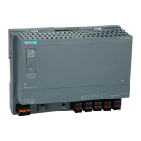
High current power supply for FireFinder-XLS/Desigo systems, providing 24VDC and charging 100AH batteries.

PSC-12 Key Features

Lists features like AC input, switch mode power, power factor correction, battery charger, and 12A output.

PSC-12 Operation and System Integration

PSC-12 Functional Components and Network Integration

Details the PSC-12's role in the HNET network, its four components, and communication with system modules.

Alarm and Trouble Relay Control Logic

Explains how ALARM and TROUBLE bus signals override commands to the alarm and trouble relays.

Power Supply Architecture and Input

Describes the off-line switch mode converter, power factor correction, and input voltage range.

Battery Charging Management

Details the charger's three charge modes (Bulk, Trickle, Float) and battery diagnostic capabilities.

Terminal Blocks, Controls, and Indicators

PSC-12 Physical Interface Elements

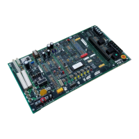
Details the PSC-12's reset switch, LEDs, HNET/CAN address switches, circuit breaker, and terminal connections.

PSC-12 Status Indicator LEDs

Defines the meaning of each status LED (POWER, MODULE FAIL, CAN FAIL, HNET FAIL, GND FAULT, 24V 12A FAIL, 24V 4A FAIL).

Ground Fault Detection Thresholds

Lists the resistance thresholds for detecting positive and negative ground faults on various terminals.

HNET/CAN Network Address Configuration

Explains the use of three rotary dial switches for setting the HNET/CAN network address of the PSC-12.

Terminal Block TB1 Connections

Details connections for TB1, including FMT riser, monitor speaker, and LVM microphone inputs.

Terminal Block TB2 Relay Outputs

Describes TB2 relay outputs for Alarm, Trouble, and User-programmable functions, including their ratings.

Terminal Block TB3: 24VDC Power Limited Output

Details the TB3 terminal for 4A power-limited 24VDC output, including shutdown conditions and wiring.

Terminal Block TB4: 24VDC Non-Power Limited Output

Details the TB4 terminal for 12A non-power-limited 24VDC output, including shutdown conditions and wiring.

Total 24VDC Output Current Limit

Specifies that the combined power-limited and non-power-limited 24VDC outputs must not exceed 12A.

Pre-Installation Checks and Components

Factory Installed Plug P4

Describes the factory-installed plug P4 and its importance for battery charging control.

Tamper Switch Connection P5

Explains the connection of the HTSW-1 Tamper Switch to P5 for door position monitoring.

Battery Connection P9

Details the connection of the backup battery to the PSC-12 via P9, emphasizing battery size calculation.

Ground Fault Supervision Jumper P10

Instructs to set the jumper on P10 to the ENABLE position for ground fault supervision.

System Connection P12 and 60-pin Connector

Describes the P12 AC input and the 60-pin connector for system communication and power.

PSC-12 Installation Kit Components

Lists the components included in the PSC-12 installation kit for various PSC-12/PTB configurations.

Installation Procedures

Pre-Installation Configuration Settings

Details required settings for the battery circuit breaker and network address switches before installation.

Mounting the PSC-12 on Mounting Plate (CAB-MP)

Provides instructions for mounting the PSC-12 on the optional CAB-MP, including alignment and screw tightening.

Wiring Connections

PSC-12 Terminal Block and Connector Locations

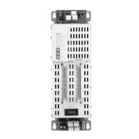
Identifies terminal blocks and connectors at the top (power-limited) and bottom (non-power-limited) of the PSC-12.

Earth Grounding Requirements

Specifies requirements for earth grounding, including using a dedicated breaker and not using conduit.

PSC-12 Wiring Diagram in CAB Enclosures

Illustrates the wiring of the PSC-12 within CAB enclosures, distinguishing between power-limited and non-power-limited wiring.

Battery Connections and Wiring

NEC Compliance for Battery Wiring

Details NEC requirements for separating power-limited conductors from other wiring types.

Connecting BTX Batteries to PSC-12

Step-by-step guide for connecting BTX batteries using the Battery Cable Conversion Kit.

Anti-Interference Capacitor Installation

Wiring the Anti-Interference Capacitor

Instructions for installing the 6.8uF, 100V bipolar capacitor between System Ground and Earth Ground.

Power Supply Load and Battery Calculations

Explains how to use the Zeus tool for calculating power supply load and battery size requirements.

Battery Power Management and Specifications

UL864 Compliance for Battery Backup

Notes the requirement for battery backup for UL864 compliance and the PSC-12's charging capacity.

UL Listed Battery Models for System

Lists UL listed battery models compatible with the FireFinder-XLS/Desigo Fire Safety Modular/Cerberus PRO Modular system.

Battery System Electrical Ratings

Provides electrical ratings for the battery system, including input voltage, current, and max charge current.

Electrical Ratings Summary

Summarizes input voltage, current, output current, and output power specifications for the PSC-12.

Cyber Security Disclaimer and Recommendations

Siemens Product Security Functions

Explains that Siemens products provide security functions as part of a comprehensive security concept.

Importance of Comprehensive Security Concepts

Stresses the need for customized, state-of-the-art security concepts for site-specific needs.

Contacting Siemens for Security Information

Advises contacting Siemens sales/project department for information on building technology security and advisories.

Related product manuals