Document No. 553-504
Installation Instructions
October 9, 2019
Siemens Industry Inc. Page 4 of 5
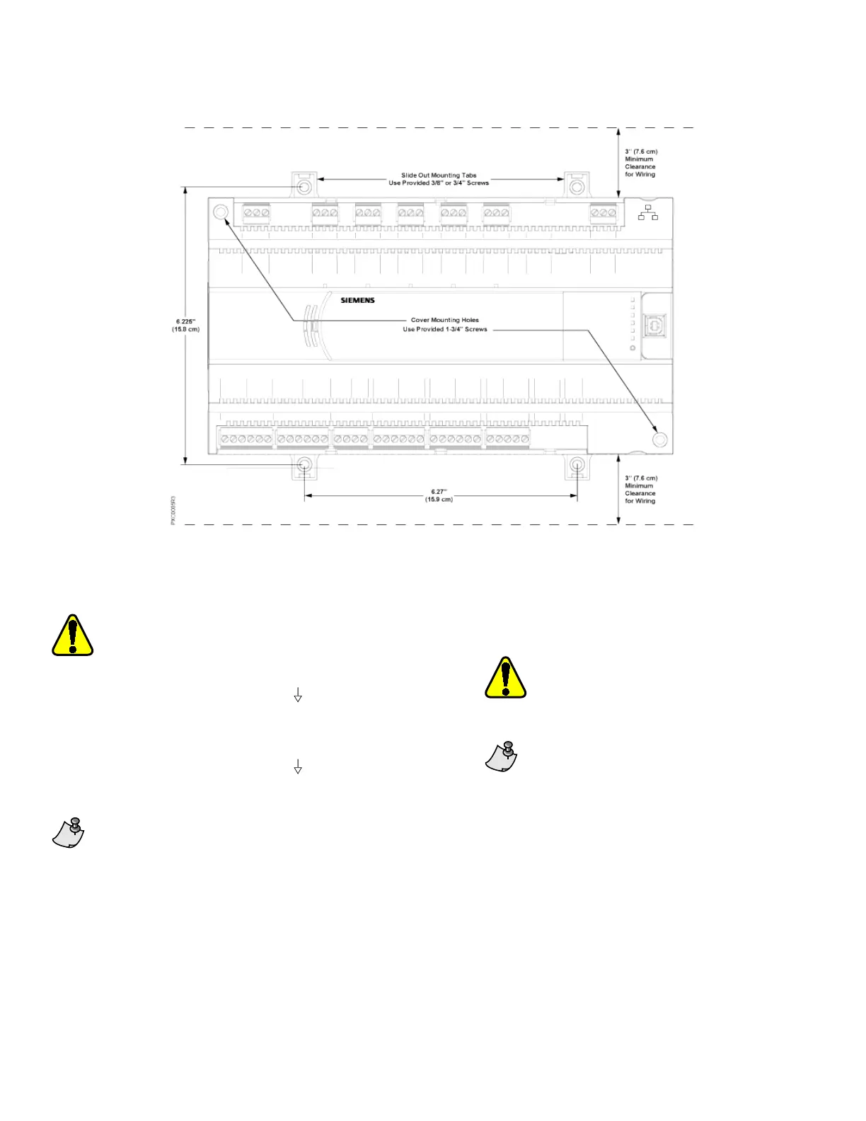
Figure 2: Compact 16/24 Dimensions for Installation.
Completing the Installation
For RS-485 ALN or FLN, terminate only one
end of the shield wire on the enclosure earth
ground.
• For a 3-wire system,
terminal is
connected to reference wire. Protective
ground terminal may be connected to
earth ground.
• For a 2-wire system,
terminal is not
connected. Protective ground terminal
must be connected to earth ground.
Do not connect the power or network
communication cable until instructed to do so
during start-up.
1. Terminate power wiring to the 24 Vac removable
plug.
2. If required, remove the RS-485 plug and terminate
the communication wiring.
3. If required, terminate wiring to the Island Bus
connector.
4. Terminate point wiring to the appropriate
connectors.
Adjacent point connections on the PXC
Compact Series share a ground
connection.
Do not connect the power or network
communication cable until instructed to
do so during start-up.The combined total
of the external sensor power outputs
cannot exceed 200 mA.
For specific wiring diagrams, see the APOGEE Wiring
Guidelines for Field Panels and Equipment Controllers
(125-3002).
The installation is now complete.
 Loading...