25 / 46
Siemens Wall-mounted sensors and room operator units for KNX/ETS and KNX/ACS CM2N1602en_05
Building Technologies ETS engineering 2018-09-14
5 ETS engineering
5.1 Engineering
The product data (*.vd5 or *.knxprod) must be downloaded from the website and
imported in the ETS for engineering. The product data is available at
www.siemens.com/hvac-td or www.siemens.com/gamma-td
.
I
f ETS3 is used, make sure to install first ETS3 patch (additional software column
SW) for ETS3.0f www.siemens.com/hvac-td
For ETS4, make sure the latest version is installed or at least version 4.1.2.
F
or a series of examples see section 5.6.
5.2 Commissioning
Prior to commissioning, all devices must be mounted as per the mounting
instructions [2] and connected to the bus via bus connector as per to the bus
topology (red to +, black to –). To check correct polarity of the wires for of a bus
participant, press the programming pin if the bus is powered. If the service LED
lights up, the polarity of the wires is correct
Short (< 2 s) Switch over to programming mode or acknowledge display of a
No functions are executed when the programming button is
pressed longer (> 2 s to 5 s).
Long (> 20 s)
Note!
Reset to factory settings.
This operation resets all user preference data and parameter
settings to factory default.
This operation is irreversible.
Device is in programming mode.
All other indication types do not apply to KNX.
D
uring parameterization using the commissioning software, the input objects are
set to default values upon initial switch-on or following standard reset.
In the event of a bus voltage failure, the device detects the failure and saves the
values received last to non-volatile memory. After bus power restoration, the saved
status of all input objects is restored. The status values received via the bus for the
LEDs of keys A1 to D2 are not stored.
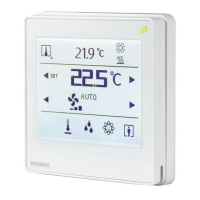
Functionality of touch
keys and display
Commissioning
prerequisites
 Loading...