52 / 58
Siemens RDF302 Basic documentation CE1P3079en
Building Technologies 07 Dec 2011
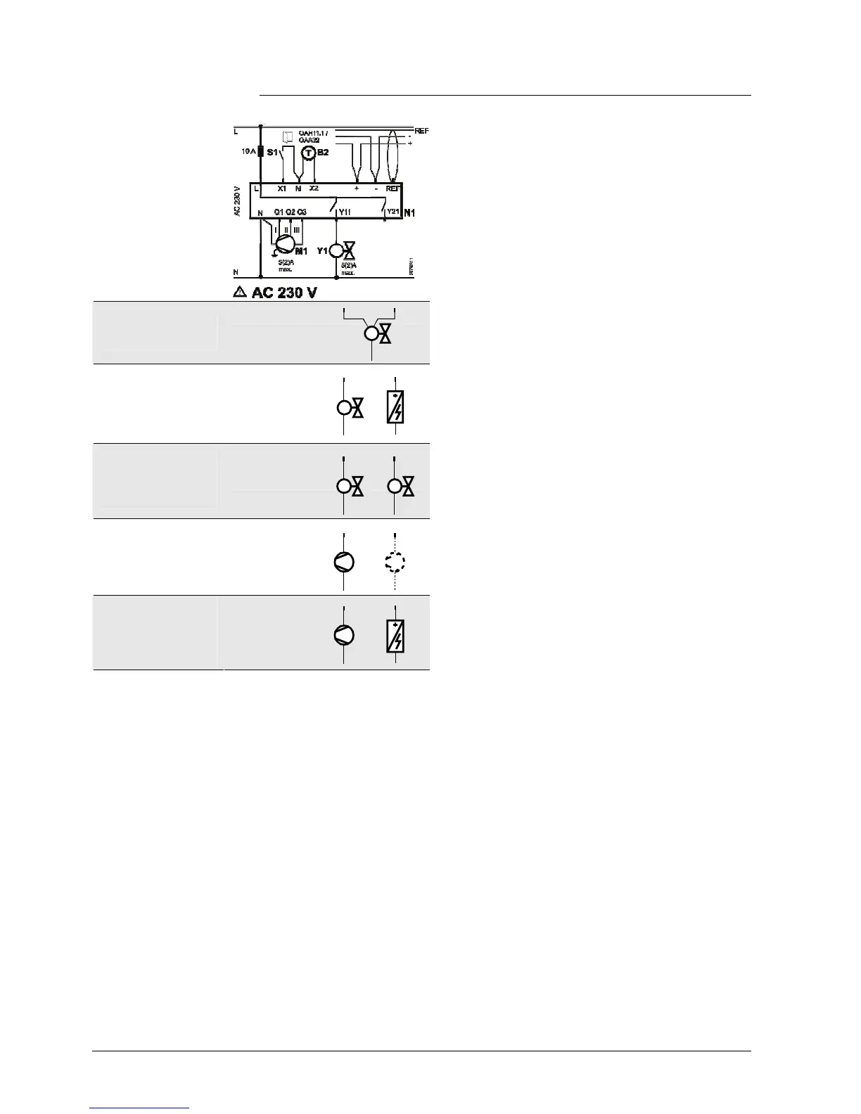
5.2 Connection diagrams
Application
2-pipe, 2-position
2-pipe, 3-position
2-pipe & electric
heater
4-pipe
1-stage compressor
(heating and/or
cooling)
1-stage compressor
& electric heater
N1 Room thermostat RDF302
M1 1-speed or 3-speed fan
Y1 Valve actuator, 2-pos or 3-pos
Y1, Y2 Valve actuator, 2-pos
E1 Electric heater
C1 1-stage compressor
F External fuse
S1, S2 Switch (keycard, window contact,
presence detector, etc.)
B1, B2 Temperature sensor (return air temp.,
external room temp., changeover
sensor, etc.)
+ RS485 Modbus connection
- RS485 Modbus connection
REF RS485 signal/common ground
(Differential common)
L
N
10 A
L
N
Y11
Y21
AC 230 V
X1 M
X2
N1
M1
Y1
5(2)A
max.
5(2)A
max.
B2
S2
B1
S1
F
3171A12
Q1 Q2 Q3
IIIIII
CE+ CE-
KNX
Y1
5(2)A
max.
E1
5(2)A
max.
5(2)A
max.
Y1
C1
5(2)A
max.
Y1
5(2)A
max.
Y2
5(2)A
max.
C1
5(2)A
max.
E1
5(2)A
max.
C2
5(2)A
max.
 Loading...