5 / 18
Siemens RDF600KN, RDF600KN/VB, RDF600KN/S A6V11425204_en--_d
Smart Infrastructure Semi flush-mount communicating room thermostats 2020-02-21
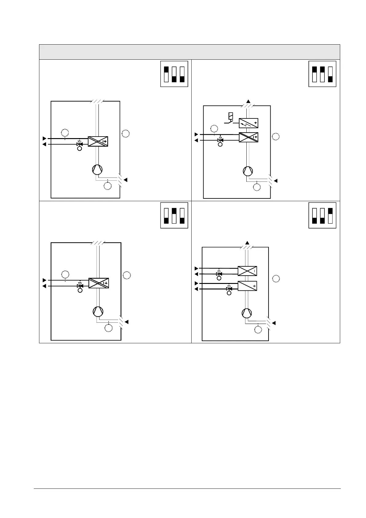
Applications for fan coil systems
Application and output signal, DIP switches, diagram
· 2-pipe fan coil unit ON/OFF
(heating or cooling)
1
ON
2 3
· 2-pipe fan coil unit with el. heater
(heating or cooling) ON/OFF
1
ON
2 3
3076D20
(B1)
M1
Y1
T
B2
T
T
(B1)
Y1
M1
3171D21
T
B2
YE
T
(B1)
T
(B1)
· 2-pipe fan coil unit 3-position
(heating or cooling)
1
ON
2 3
· 4-pipe fan coil unit ON/OFF
(heating and cooling)
1
ON
2 3
3076D20
(B1)
M1
Y1
T
B2
T
T
(B1)
T
Y2
Y1
M1
3076D22
(B1)
T
(B1)
Y1 Heating or heating/cooling valve
actuator
B1 Return air temperature sensor or external room
temperature sensor (optional)
Y2 Cooling valve actuator B2 Changeover sensor (optional)
YE Electric heater M1 1-speed or 3-speed fan
N1 Thermostat
 Loading...