10/14
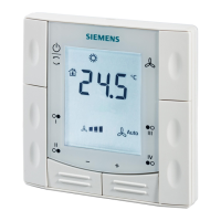
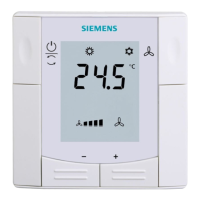
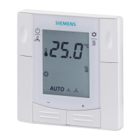
Siemens RDF300…/RDF340 / RDF400… / RDF600... Flush-mounted Room thermostats CE1N3076en
Building Technologies 2018-12-27
· The control sequence may need to be set via parameter P01 depending on the
application. The factory setting for the 2-pipe application is “Cooling only”; and
“Heating and Cooling” for the 4-pipe application.
· When the thermostat is used with a compressor, the minimum output on-time
(parameter P48) and off-time (parameter P49) for Y11/Y21 must be adjusted to
avoid damaging the compressor and shortening its life.
· Recalibrate the temperature sensor if the room temperature displayed on the
thermostat does not match the room temperature measured (after min. 1 hour of
operation). To do this, change parameter P05.
We recommend to review the setpoints and setpoint ranges (parameters P08…P12)
and change them as needed to achieve maximum comfort and save energy.
Disposal
The device is considered electrical and electronic equipment for disposal in terms of the
applicable European Directive and may not be disposed of as domestic garbage.
· Dispose of the device through channels provided for this purpose.
· Comply with all local and currently applicable laws and regulations.
Technical data
Rated voltage RDF300… /400… / 600...
RDF340…
AC 230 V
SELV AC 24 V± 20 % or
AC 24 V class 2 (US)
Frequency 50/60 Hz
Power consumption RDF300... / RDF400.. RDF340…
RDF600…
Max. 8 VA
Max. 3.5 VA / 0.8 W
External supply line protection (EU)
Circuit breaker max. 10 A
Characteristic B, C, D
according to EN 60898
or
Power source with current
limitation of max. 10 A
No internal fuse
External preliminary protection with max. C 10 A circuit breaker in the supply line
equired under all circumstances
Fan control Q1, Q2, Q3-N
Rating
AC 230 V
5 mA...5(2) A
Control output Y11-N/Y21-N (N.O.)
Rating
AC 230 V
5 mA...5(2) A
Control output Y10-G0/Y20-G0
Resolution
Current
SELV DC 0…10 V
39 mV
Max. ± 1 mA
Max. total load current through terminal "L" (Qx + Yxx)
Max. 7 A
Multifunctional input X1-M/X2-M
Temperature sensor input:
Type
Temperature range
Cable length
Digital input:
Operating action
Contact sensing
Parallel connection of several thermostats
for one switch
Insulation against mains voltage (SELV)
NTC (3 kW at 25 °C)
0...49 °C
Max. 80 m
Selectable (N.O./N.C.)
SELV DC 0...5 V/max. 5 mA
Max. 20 thermostats per
switch
4 kV, reinforced insulation
Control sequence
Compressor-based
application
Calibrate sensor
Setpoint and range
limitation
Power supply
Outputs
Inputs

 Loading...
