Installing the Device
2.5Connecting the Failsafe Alarm Relay
5. Using two #6-32 screws for each adapter, secure the device to the panel.
2.5 Connecting the Failsafe Alarm Relay
The failsafe relay can be configured to latch based on alarm conditions. The NO
(Normally Open) contact is closed when the unit is powered and there are no ac-
tive alarms. If the device is not powered or if an active alarm is configured, the relay
opens the NO contact and closes the NC (Normally Closed) contact.
Note
Control of the failsafe relay output is configurable through RUGGEDCOM RS900G .
One common application for this relay is to signal an alarm if a power failure occurs.
For more information, refer to the RUGGEDCOM RS900G User Guide for the RUGGED-
COM RS900G.
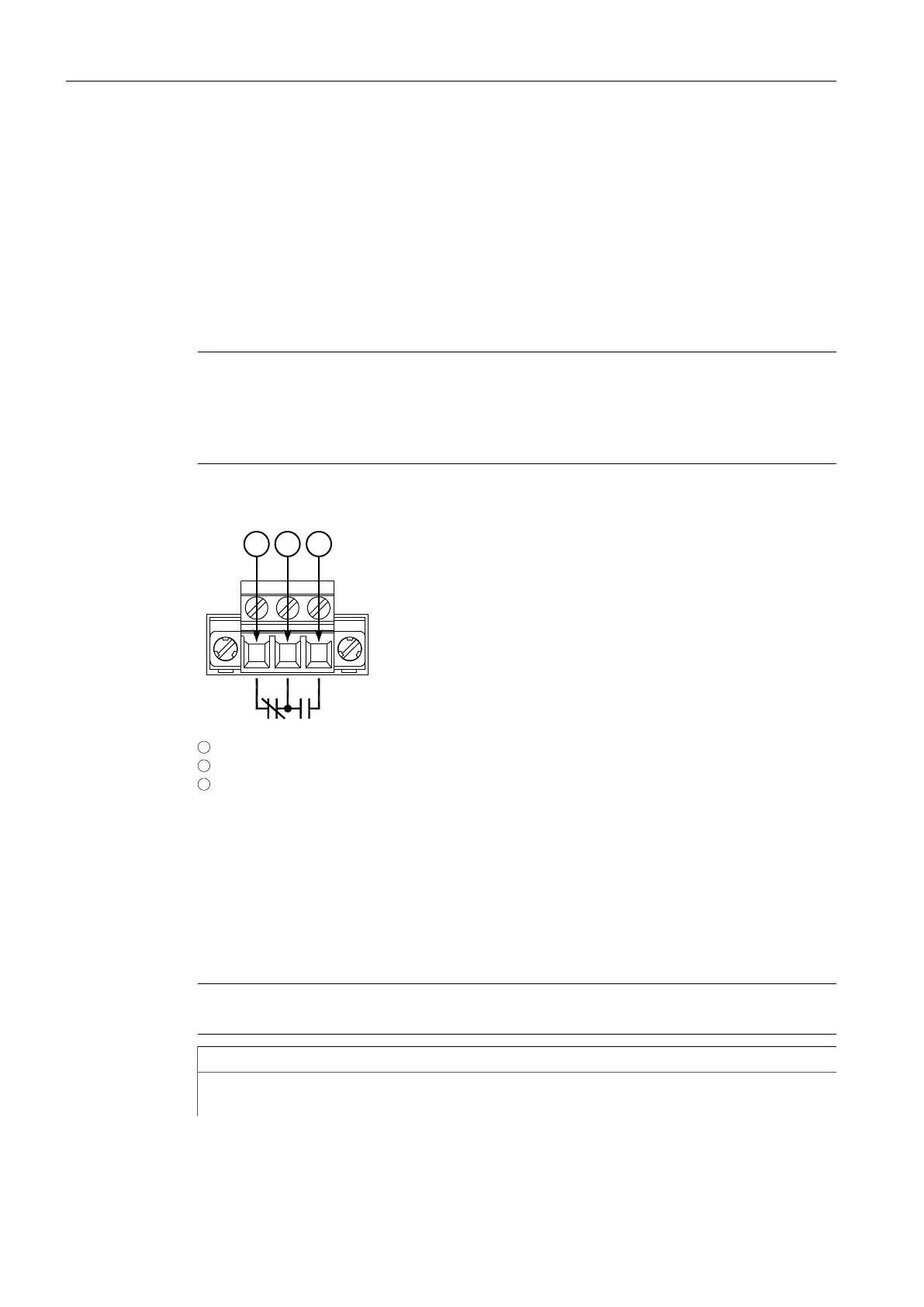
The following shows the proper relay connections.
1
Normally Closed
2
Common
3
Normally Open
Figure2.5 Failsafe Alarm Relay Wiring
2.6 Connecting Power
The RUGGEDCOM RS900G features an integrated high AC/DC or low DC power supply
that accepts input from redudant power sources.
Note
Power sources can be connected to either power supply terminal block on the device.
IMPORTANT
• For 110/230 VAC rated equipment, an appropriately rated AC circuit breaker
must be installed.
RUGGEDCOM RS900G
Installation Manual, 06/2020, C79000-G8976-1025-07
11
 Loading...