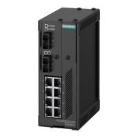
Installing the Device
2.6.2Connecting Low DC Power
Before testing the dielectric strength (HIPOT) in the field, remove the braided
ground cable connected to the surge ground terminal and chassis ground. This cable
connects transient suppression circuitry to chassis ground and must be removed to
avoid damage to transient suppression circuitry during testing.
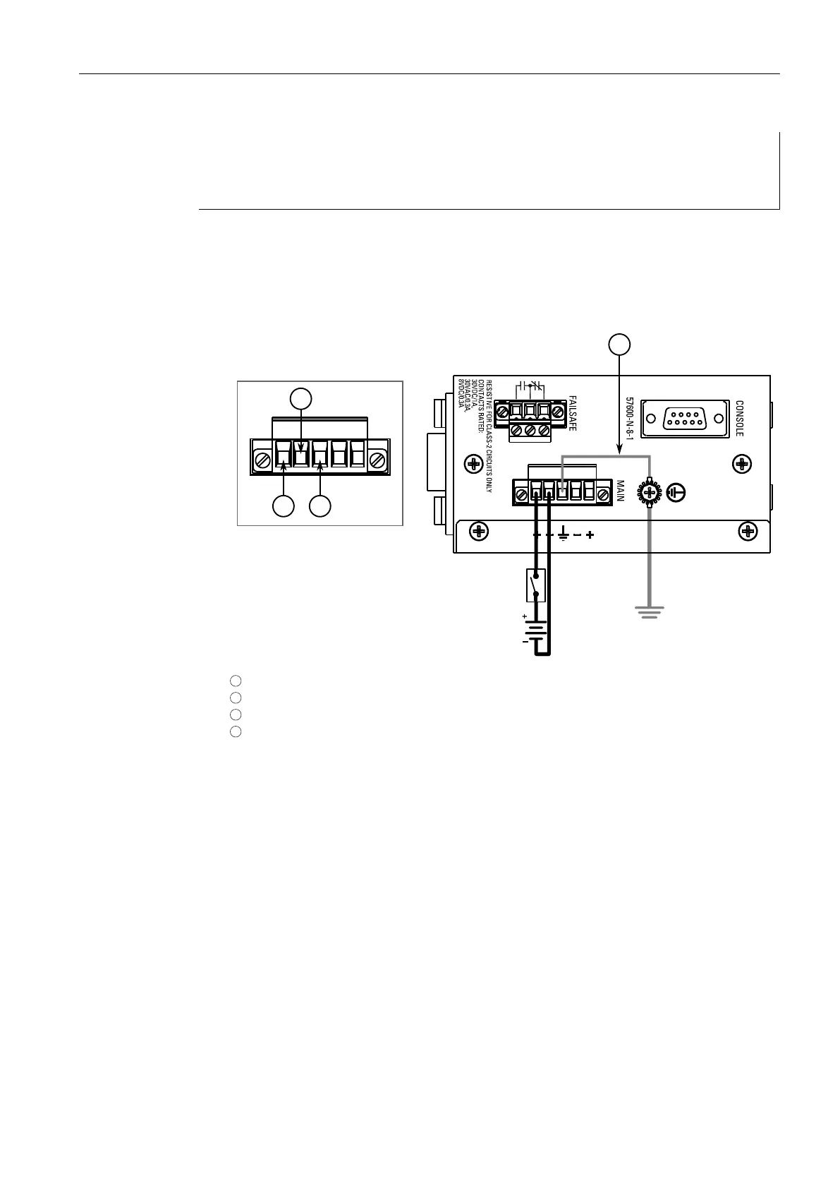
1. Secure a European-style terminal block (or Euroblock) to one of the available ter-
minals.
2. Connect the positive wire from the power source to the positive terminal on the
terminal block.
1
Positive Terminal
2
Negative Terminal
3
Surge Ground Terminal
4
Braided Ground Cable
Figure2.7 Terminal Block Wiring – Single DC Power Supply Inputs
3. Connect the negative wire from the power source to the negative terminal on
the terminal block.
4. Using a braided wire or other appropriate grounding wire, connect the surge
ground terminal to the chassis ground connection. The surge ground terminal is
used as the ground conductor for all surge and transient suppression circuitry in-
ternal to the unit.
5. Connect the ground terminal on the power source to the chassis ground termi-
nal on the device.
6. If a redundant power source is required, repeat Step 1 to Step 5 using the sec-
ond terminal.
14
RUGGEDCOM RS900G
Installation Manual, 06/2020, C79000-G8976-1025-07
 Loading...