RUGGEDCOM WIN5214
Installation Guide
Chapter 2
Installing the Subscriber Unit
Mounting the Subscriber Unit to a Pole 13
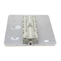
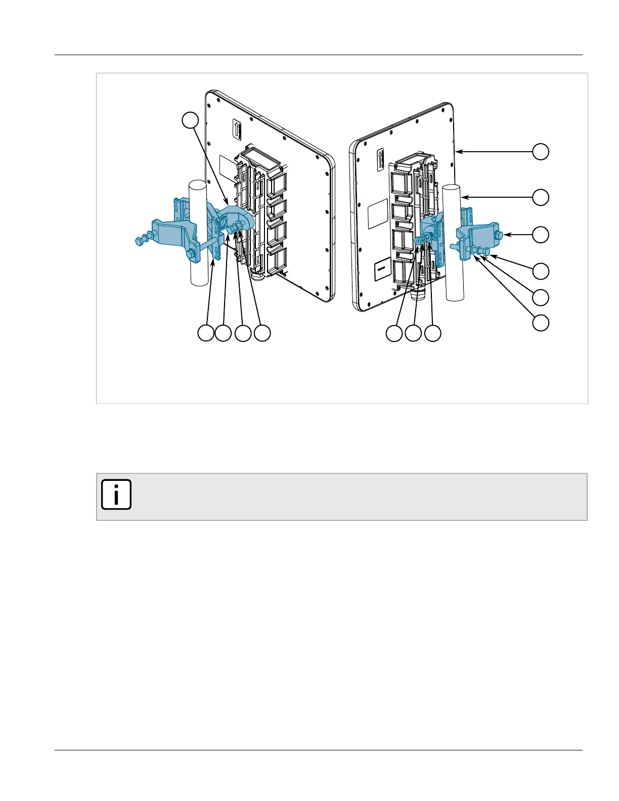
Figure5:Mounting the Subscriber Unit to a Small Pole
1.Subscriber Unit 2.Pole 3.Clamping Bracket 4.Mounting Bracket 5.M8-25 Hex Screw 6.M8 Spring Washer 7.M8 Flat
Washer 8.M8 Nut 9.M8-70 Hex Screw
2. Liberally apply an anti-corrosion spray to all galvanized steel components, including mounting brackets, nuts,
washers and screws.
3. Select a mounting location on the pole.
4. Position the mounting bracket against the pole.
NOTE
When mounting the subscriber unit, note the orientation of the clamping bracket in Figure 4 or
Figure 5.
5. Secure the clamping bracket to the mounting bracket using screws, spring washers and nuts. Make sure the
screws are hand tightened.
6. Point the front face of the subscriber unit in the general direction of the designated base station.
7. Make sure the PWR LED on the subscriber unit is on.
8. Position the subscriber unit until the maximum RSSI link quality reading is achieved. A single RSSI LED
indicates the subscriber unit is at minimum synchronized with the base station. For information about the
RSSI LED indicators, refer to Section1.2, “Description”.
If the subscriber unit is not synchronized with the base station, make sure the subscriber unit is properly
configured. For more information, refer to the RUGGEDCOM WIN SU User Guide.
If the expected link quality still cannot be achieved, try to improve the reception quality by placing the
subscriber unit at a higher point or in an alternate location.
9. Make sure the subscriber unit is properly grounded according to local standards. For more information, refer
to Section2.6, “Grounding the Subscriber Unit”.
 Loading...