109/126
Siemens Building Technologies Basic documentation RVD240 CE1P2384en
HVAC Products 32 Engineering 27.05.2004
32 Engineering
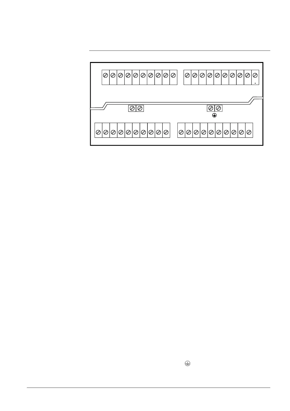
32.1 Connection terminals
1 2 3 4 5 6 7 8 9 10 11 12 13 14 15 16 17 18 19 20
1 2 3 4 5 6 7 8 9 10 11 12 13 14 15 16 17 18 19 20
2383Z03
A6 MD B9 B1 M B3 B7
B71
/U1
MMH5
NL
F1
Y1 Y2
F3 Q1
F4 Y5
Y6
F7
N
DB MB P1 B31B72
B32 B12
CM
+
CM
--
Q3 Q2
--
F6
Y7
Q4
Y8
K6
A6 PPS, connection of room unit / room sensor QAW70, QAW50..., QAA10
B1 Flow sensor heating circuit 1 or common flow (depending on the type of plant)
B12 Flow sensor heating circuit 1 or 2 (depending on the type of plant)
B3 Flow sensor d.h.w. or flow or return sensor heating circuit 2 (depending on the type of plant)
B31 Storage tank sensor
B32 Storage tank or return sensor (depending on the type of plant)
B7 Primary return sensor
B71 / U1 Return sensor / analog input DC 0...10 V
B72 Return sensor
B9 Outside sensor
CM– Digital M-bus connection facility (bipolar)
CM+ Digital M-bus connection facility (bipolar)
DB LPB connection facility
H5 Digital input (heat meter pulses, alarms, flow switch, heat demand etc.)
M Ground for sensors (analog)
MB LPB ground
MD Ground for PPS (digital)
P1 PWM output for speed-controlled pumps
L Live conductor AC 230 V
N Neutral conductor AC 230 V
F1 Input for Y1 and Y2
Y1 Control output for valve on the primary side OPEN
Y2 Control output for valve on the primary side CLOSED
F3 Input for Q1 and Q3
Q1 Control output for heating circuit pump ON
Q3 Control output for d.h.w. intermediate circuit, storage tank charging or circulating pump (depending
on the type of plant)
F4 Input for Y5 and Y6
Y5 Control output for valve OPEN (depending on the type of plant)
Y6 Control output for valve CLOSED (depending on the type of plant)
F7 Input for Q2
Q2 Heating circuit or storage tank charging pump ON (depending on the type of plant)
F6 Input for Y7/Q4 and Y8/ K6
Y7 Control output for valve OPEN (depending on the type of plant)
Y8 Control output for valve CLOSED (depending on the type of plant)
Q4 Control output for d.h.w. intermediate circuit / storage tank charging pump ON (depending on the
type of plant)
K6 Control output for circulating pump ON
The base contains 2 auxiliary terminals N and
Low voltage
Mains voltage side

 Loading...


