22/126
Siemens Building Technologies Basic documentation RVD240 CE1P2384en
HVAC Products 3 Fundamentals 27.05.2004
B9
Q1
Y1
B7
B1
B71
B12
Q2
Y7
B71
A6A6
B72
Y5
B3
B32
Q3
Q
B31
b)
a)
2384S13
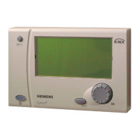
A6 Room units
B1 Sensor common heating circuit flow
B12 Flow sensor heating circuit 2
B3 Flow sensor d.h.w. circuit
B31 Storage tank sensor 1
B32 Storage tank sensor 2
B7 Sensor common primary return heating circuit*
B71 Sensor common secondary return heating circuit or
return sensor heating circuit 2
B72 Return sensor primary d.h.w. circuit
B9 Outside sensor
Q Circulating pump (controlled externally, optional)
Q1 Pump heating circuit 1
Q2 Pump heating circuit 2
Q3 Storage tank charging pump
Y1 2-port valve common heating circuit flow
Y5 2-port valve d.h.w. primary return
Y7 Mixing valve heating circuit 2
B9
Q1
Y1
B7
B1
B71
B12
Q2
Y7
B71
A6A6
B31
B72
2384S14
Y5
B32
B3
Q3
Q
A6 Room units
B1 Sensor common heating circuit flow
B12 Flow sensor heating circuit 2
B3 Flow sensor d.h.w. circuit
B31 Storage tank sensor 1
B32 Storage tank sensor 2
B7 Sensor common primary return heating circuit*
B71 Sensor common secondary return heating circuit or
return sensor heating circuit 2
B72 Return sensor primary d.h.w. circuit
B9 Outside sensor
Q Circulating pump (controlled externally, optional)
Q1 Pump heating circuit 1
Q2 Pump heating circuit 2
Q3 D.h.w. intermediate circuit pump
Y1 2-port valve common heating circuit flow
Y5 2-port valve d.h.w. primary return
Y7 Mixing valve heating circuit 2
a) Circulating pump feeding water into the heat exchanger’s return
b) Circulating pump feeding water into the storage tank
* Suppression of hydraulic creep
3.2 Operating modes
3.2.1 Heating circuit control
The RVD240 offers the following operating modes:
Automatic operation
• Automatic heating operation, changeover between the nominal room
temperature and the reduced room temperature according to the time
program
• Demand-dependent switching of the heating system as a function of the
outside temperature while giving consideration to the building's thermal
inertia (ECO function)
• Remote operation via room unit (optional)
• Frost protection is ensured
Continuous operation
• Heating mode with no time program
• Heating to the temperature adjusted with the setting knob
• Automatic ECO function inactive
• Frost protection is ensured
Standby
• Heating operation at the frost level
• Frost protection is ensured
 Loading...
