Displays and connectors
2.3 Electrical connections
SIMATIC CM 1242-5
16 Operating Instructions, 01/2023, C79000-G8976-C245-06
DIAG
(red / green)
-
RUN/STOP
(yellow /
ERROR
(red)
Meaning
No master-slave connection detected.
PROFIBUS cable not connected or not detected.
In STOP mode, configuring and performing diagnostics on the CM remain possible.
2.3 Electrical connections
Power supply
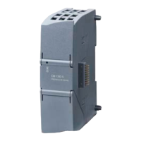
The CM 1242-5 is supplied with power from the backplane bus. It does not require a separate
power supply.
9-pin D-sub female connector (PROFIBUS)
The PROFIBUS connector is located behind the lower cover of the module. The interface is a
9-pin D-sub female connector operating according to the RS-485 standard.
You also have the option of connecting to optical PROFIBUS networks via an Optical Bus
Terminal OBT or an Optical Link Module OLM.
You will find the pin assignment of the D-sub socket in section Pinout of the D-sub socket
(Page 42).
More detailed information on the electrical connections
For technical information on the electrical connections, refer to the section Technical data
(Page 41).

 Loading...


