Network module (SAFEDLINK) FN2001
1
7
Siemens Industry, Inc. A6V10315042_f_en_--
Building Technologies Division 2015-04-16
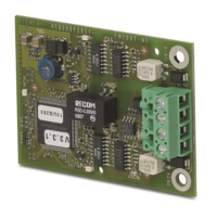
1.4 Views
H3 H2
H1
1
1
1
RUN
1 2
Network module (SAFEDLINK) FN2001
X1 Connector to the PMI & mainboard (connector on rear panel)
X2 Connector to the FCnet/C-WEB circuits (connector on rear); not used with FS20/FS920
X3 Connector to FCnet/C-WEB circuits; used with FS20/FS920
H1 LED green: Status display for network module
H2 LED yellow: Status display for circuit 2
H3 LED yellow: Status display for circuit 1
1.5 Pin assignments
1.5.1 Connector X3
Pin Designation Description
4 A1 Circuit 1 (+)
3 B1 Circuit 1 (–)
2 A2 Circuit 2 (+)
1 B2 Circuit 2 (–)
Admissible cable cross-section: 12…22 AWG
 Loading...


