12
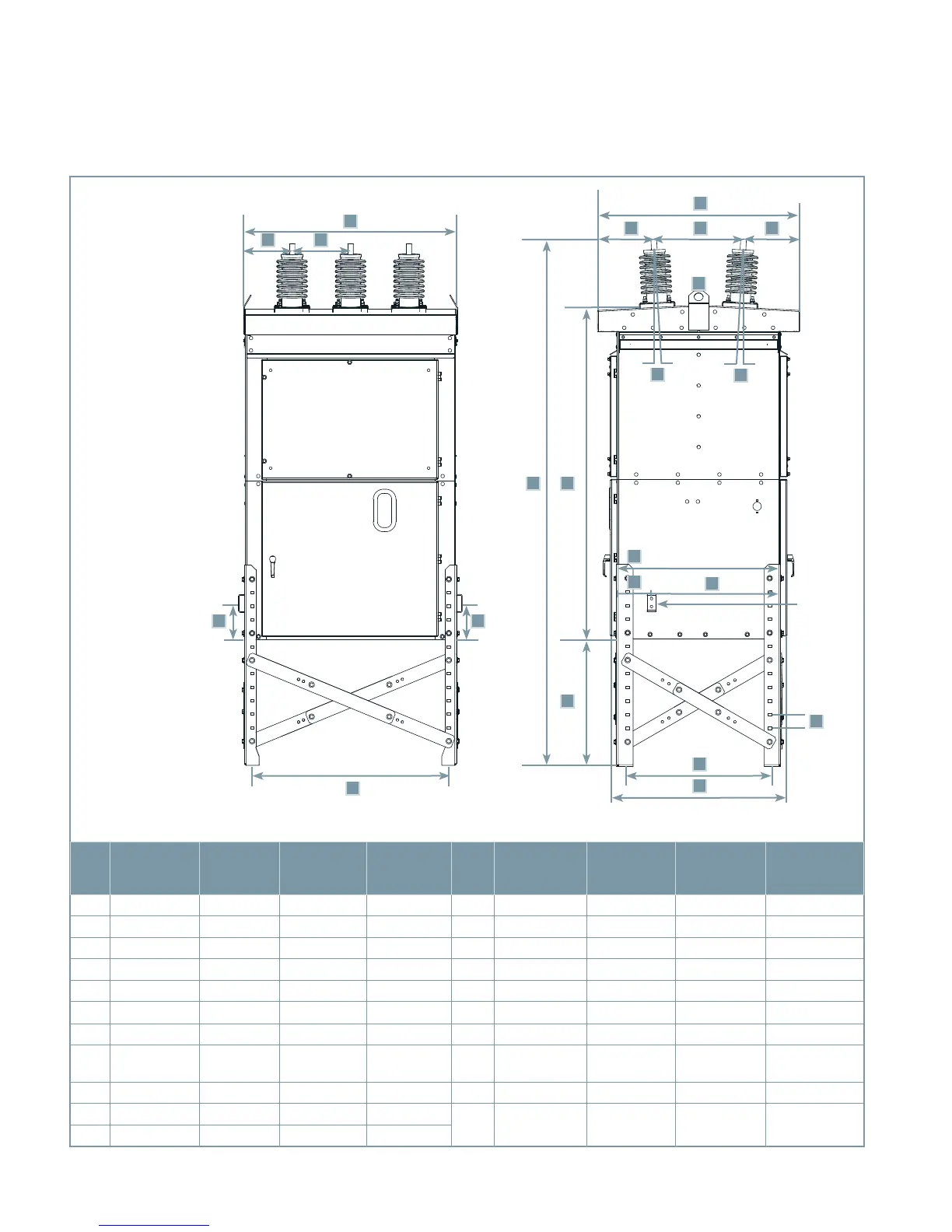
Figure 3: Outline drawing
1
2-4-6 1-3-5
Item
15.5 kV
1,200 A-
2,000 A
15.5 kV
3,000 A
27.6 kV
1,200 A-
2,000 A
38.0 kV
1,200 A-
2,500 A
Item
15.5 kV
1,200 A-
2,000 A
15.5 kV
3,000 A
27.6 kV
1,200 A-
2,000 A
38.0 kV
1,200 A-
2,500 A
A 47.1 (1,196) 56.3 (1,430) 56.3 (1,430) 65.7 (1,669) L 3.0° 3.0° 3.0° 3.0°
B 10.6 (269) 12.1 (307) 12.1 (307) 13.4 (340) M 35.8 (909) 44.2 (1,123) 44.0 (1,118) 55.6 (1,412)
C 13.0 (330) 16.0 (406) 16.0 (406) 19.5 (495) N 7.6 (193) 7.7 (196) 7.6 (193) 9.5 (241)
D 2.0 (51) 2.0 (51) 2.0 (51) 2.0 (51) O 28.4 (721) 36.5 (927) 36.4 (925) 46.1 (1,171)
E 8.0 (203) 8.0 (203) 8.0 (203) 8.0 (203) P 3.0 (76) 3.0 (76) 3.0 (76) 3.0 (76)
F 42.7 (1,085) 52.0 (1,321) 52.0 (1,321) 63.1 (1,603) Q 31.3 (795) 39.4 (1,001) 39.4 (1,001) 50.9 (1,293)
G 44.5 (1,130) 57.8 (1,468) 49.6 (1,260) 63.2 (1,605) R 38.8 (986) 47.0 (1,194) 46.8 (1,189) 58.4 (1,483)
H 8.0 (203) 18.4 (467) 11.5 (292) 20.4 (518) S
4.0 (102)-
28.0 (711)
4.0 (102)-
28.0 (711)
4.0 (102)-
28.0 (711)
4.0 (102)-
28.0 (711)
I 19.8 (503) 21.0 (307) 21.0 (307) 22.2 (564) T 73.5 (1,867) 77.2 (1,961) 77.6 (1,971) 93.5 (2,375)
J 8.0 (203) 18.4 (467) 11.5 (292) 20.4 (518)
U
92.0 (2,337)-
116.0 (2,945)
96.0 (2,337)-
120.0 (3,048)
96.0 (2,337)-
120.0 (3,048
120.5 (3,061)-
144.5 (3,670)
K 3.0° 3.0° 3.0° 3.0°
Note 1
Note 1
Note 1: Shown with
optional cross-bracing
for high-seismic
loading, and with legs
installed at maximum
height 28" (711 mm).
Dimensions in inches
(mm)
Relay and
control
compartment
Operator
compartment
Ground
pads on
diagonally
opposite
corners
High-voltage
compartment
A
C
B
E E
F
G
H
I
J
D
K
L
TU
S
Q
R
P
N
O
M