52
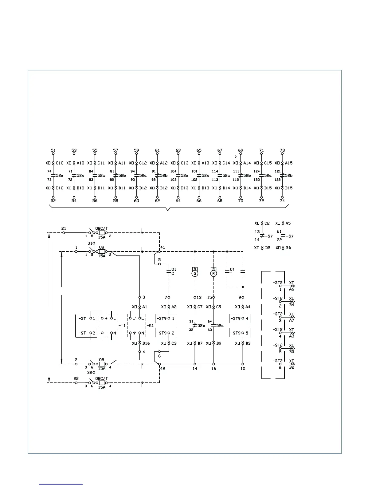
Figure 11: Typical control schematic for magnetic-actuator operator
4
1
1
52a and 52b spare contacts (standard)
CLOSE/OPEN
power
Power
Electronic
controller
Electronic
controller
Electronic
controller
Electronic
controller
Power
input
Power
supplyt
Filter
CLOSE
command
OPEN
command
Status
Footnotes 1 and 2
Footnote 3
Footnote 3
Footnotes 1 and 2
Footnotes:
1.
Use this connection when high-range electronic controller power supply specified and high-range binary input (commands) specified.
Input to close and trip (commands) circuits ≥ 68 Vac or 68 Vdc.
2.
Use this connection when low-range electronic controller power supply specified and low-range binary input (commands) specified. Input
to close and trip (commands) circuits ≥ 17 Vac or 17 Vdc.
3.
Separate close/trip input power required when high-range electronic controller power supply specified and low-range binary input
(commands) -ST9-1/-ST9-2 and -ST9-4/-ST9-5. Low-range binary input (commands) requires ≥ 17 Vac or 17 Vdc.
4.
Schematics are shown with circuit breaker open.
Legend:
01/C Control switch close (remote)
01/T Control switch trip (remote)
08 Power disconnect
08C/T Close/open power disconnect (optional)
52a Auxiliary switch, open when circuit
breaker is open
52b Auxiliary switch, closed when circuit
breaker is open
G Green indicating light (remote)
R Red indicating light (remote)
S7 Emergency trip status
W White indicating light (remote)
XO Plug connector (operator connections)
-K1 Power supply
-T1 Filter
Protective
relays
Ready for CLOSE/
OPEN (N.O.)
Ready for OPEN
(N.O.)
Not ready (alarm)
(N.C.)
Circuit breaker
CLOSED (N.O.)
Circuit breaker
OPEN (N.O.)
Common
Contacts shown
with emergency
trip handle in
NORMAL position
Emergency trip status