49
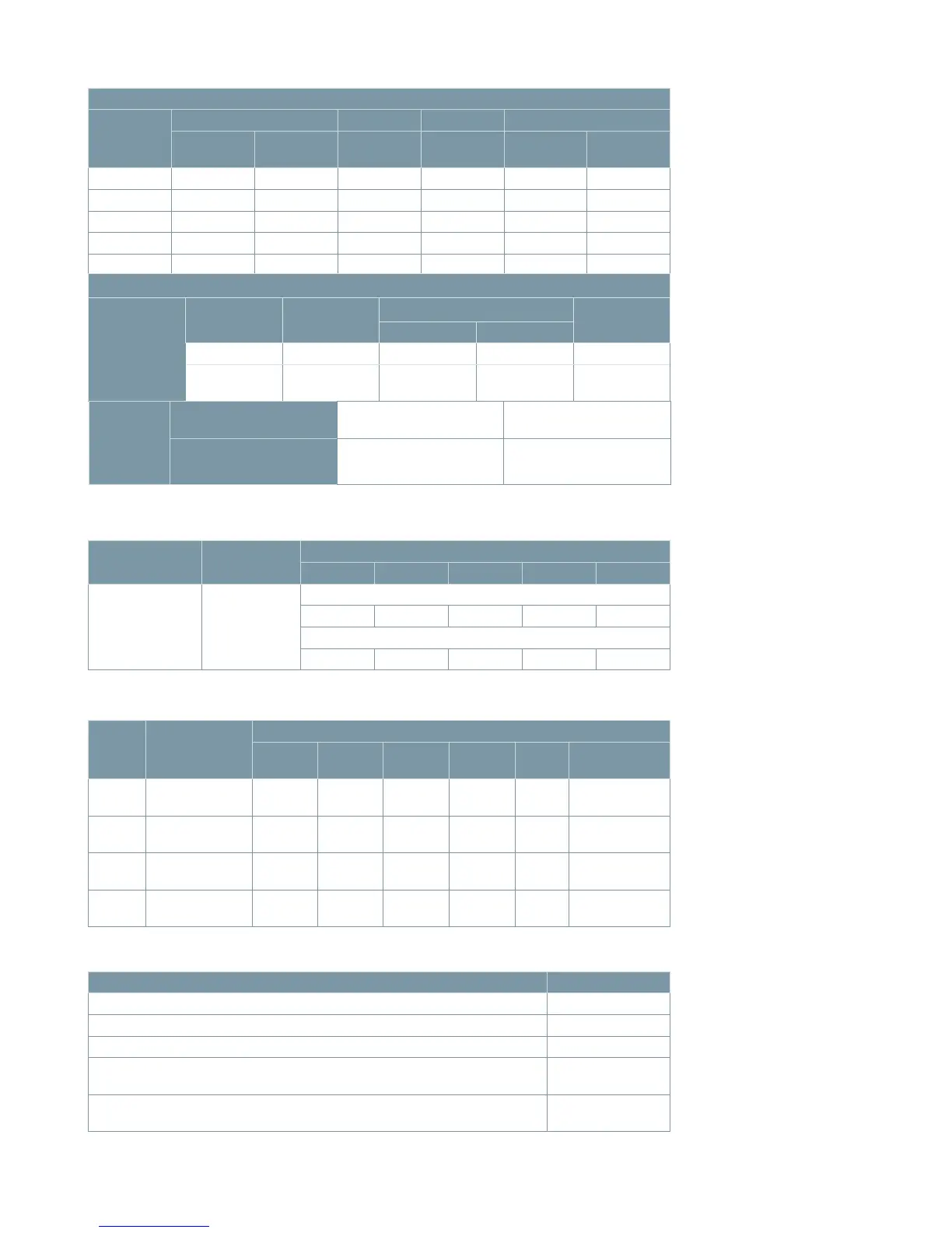
Table 11: Control data
Type auxiliary
switch
Continuous
current A
Control circuit voltage
120 Vac 240 Vac 48 Vdc 125 Vdc 250 Vdc
Circuit breaker
auxiliary switch
10
Non-inductive circuit interrupting capacity in A
10 5 10 9.6 4.8
Inductive circuit interrupting capacity in A
6 3 10 6 3
Table 12: Interrupting capacity auxiliary switch contacts
Voltage Interrupting
Continuous current
1,200 A
1,2
2,000 A
1,2
2,500 A
1,2
3,000 A
1,2
Pallet
Seismic
cross braces
15.5 kV 20/25 kA
2,519
(1,143)
2,629
(1,192)
---- ----
71
(32)
90
(41)
15.5 kV 31.5/40 kA
2,581
(1,171)
2,649
(1,202)
----
3,127
(1,418)
71
(32)
90
(41)
27.6 kV 20/25 kA
2,809
(1,274)
2,919
(1,324)
---- ----
84
(38)
110
(50)
38.0 kV 20/25/31.5/40 kA
3,956
(1,794)
3,984
(1,807)
4,075
(1,848)
----
125
(57)
130
(59)
Table 13: Type SDV7 distribution circuit breaker weight in lbs (kg)
3
Location Heater wattage
High-voltage compartment 15.5 kV and 27.6 kV 500
1
High-voltage compartment 38.0 kV 750
1
Relay and control compartment 100
1
Operator compartment - stored-energy operator
(for application below -30 °C down to -50 °C)
150
2
Operator compartment - magnetic-actuator operator
(for application below -25 °C down to -50 °C)
150
2
Table 14: Space heater data
Footnotes:
1
Thermostat controlled and set to
turn off at 95 °F.
2
Thermostat controlled and set to
turn off at 10 °F.
Stored -energy operator
Nominal
Range Close coil Trip coil
1, 6
Spring charging motor
Close Trip A A
Amperes
run (avg.)
Charging
seconds
48 Vdc 36-56 28-56 11.4 30/11.4 8 10
125 Vdc 90-140 70-140 2.1 7.4/4.8 4 10
250 Vdc 180-280 140-280 2.1 9.6/4.2 2 10
120 Vac 104-127 104-127 2.0 --- 6 10
240 Vac 208-254 208-254 2.0 --- 3 10
Magnetic-actuator operator
Electronic
controller
power supply
Input voltage
range
Input power
Controller output
Capacitor
voltage
2,3,4
Close Open
28-56 Vdc 80 W
5
40-55 A 10-15 A 160 Vdc
95-250 Vdc/
100-254 Vac
60 W/60 VA
5
40-55 A 10-15 A 160 Vdc
Binary
inputs
(close and
open
commands)
Low range model
≥ 17 Vdc or 17 Vac
Recommended duration ≥
100 ms
High range model
≥ 69 Vdc or 53 Vac
Recommended duration ≥
100 ms
Footnotes:
1
First value is for standard 50 ms/
three-cycle interrupting time.
Second value is for optional 83 ms/
five-cycle interrupting time (stored-
energy operator only).
2
If controller power fails,
capacitors retain sufficient charge
to open circuit breaker within
300 seconds, with minimum open
command duration 100 ms.
3
Capacitors discharge to 10 V or
less within five minutes after
disconnecting plug.
4
Capacitor charging time
approximately 30-35 seconds
from complete discharge,
approximately 12 seconds after
OPEN-CLOSE-OPEN sequence.
5
On initial energization, power
demand is approximately 100 W,
declining to approximately 20 W
when capacitors are fully charged.
When the circuit breaker operates
(open or close), power demand
again increases to approximately
100 W, declining to approximately
20 W when capacitors are fully
charged.
6
For stored-energy operator, power
requirement for second trip coil is
approximately 70 W (dc) or 50 VA
(ac). Power requirement for
undervoltage device is
approximately 20 W (dc) or
20 VA (ac).
Footnotes:
1
Weight does not include shipping
pallet.
2
Weight does not include seismic
cross braces.