51
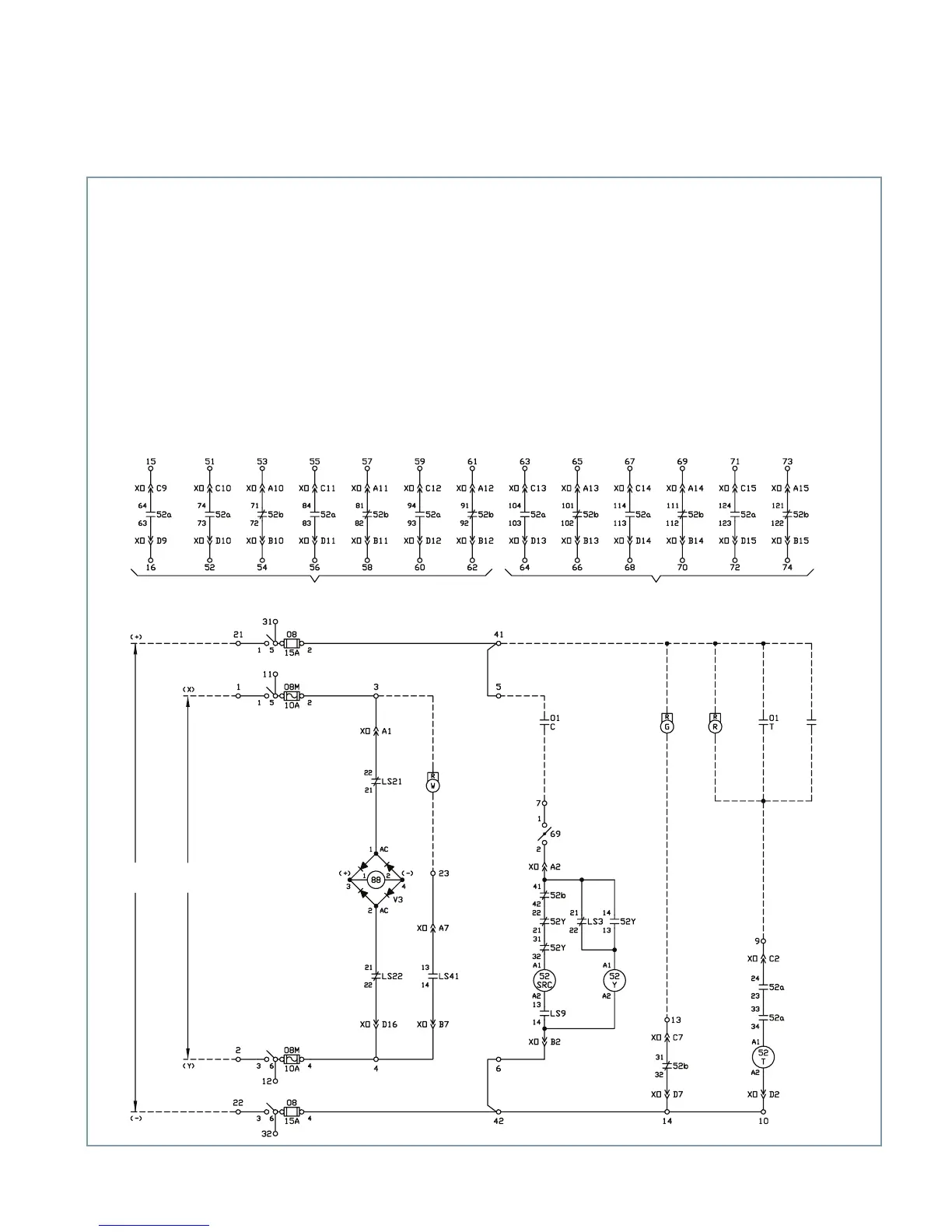
Figure 10: Typical control schematic for stored-energy operator
52a and 52b spare contacts (standard) 52a and 52b spare contacts (optional)
AC power
supply
DC power
supply
Protective
relays
Legend
01/C Control switch close (remote)
01/T Control switch trip (remote)
08 Close and trip power disconnect
08M Motor power disconnect
52a Auxiliary switch, open when circuit
breaker is open
52b Auxiliary switch, closed when
circuit breaker is open
52SRC Closing spring release coil
52T Opening spring release coil
52Y Anti-pump relay
69 Closing cutout switch
88 Spring charge motor
G Green indicating light (remote)
R Red indicating light (remote)
LS3 Closing spring position switch, closed
when closing spring is discharged
LS9 Closing spring position switch, open
when closing spring is discharged
LS21 Motor cutoff switch, closed when
closing spring is discharged
LS22 Motor cutoff switch, closed when
closing spring is discharged
LS41 Closing spring position switch, open
open when closing spring is discharged
W White indicating light (remote)
XO Plug connector (operator connections)
Schematic shown with closing
springs discharged and circuit
breaker open.