s l SENTRON 3/6 Bus Plug with Optional SEM3™ Package
Note: Cable management is highly recommended to avoid
damage or accidental disconnection of communication cables.
Siemens offers a cable management system to best protect
communication cable wiring. This system has catalog number
BPSCMK12 and may be routed on any flat surface or the busway
per user preference. This kit consists of 12 24-inch spines.
2) CAT6 Ethernet cables are required to transmit data from the
SEM3™ controller to an upstream data management system.
The port labeled PC shown in Figure 5 is the data output port
and should be used for connecting to upstream data
management systems. Multiple CAT6 cables may be
connected via an Ethernet switch shown in Figure 5 below
(sold separately).
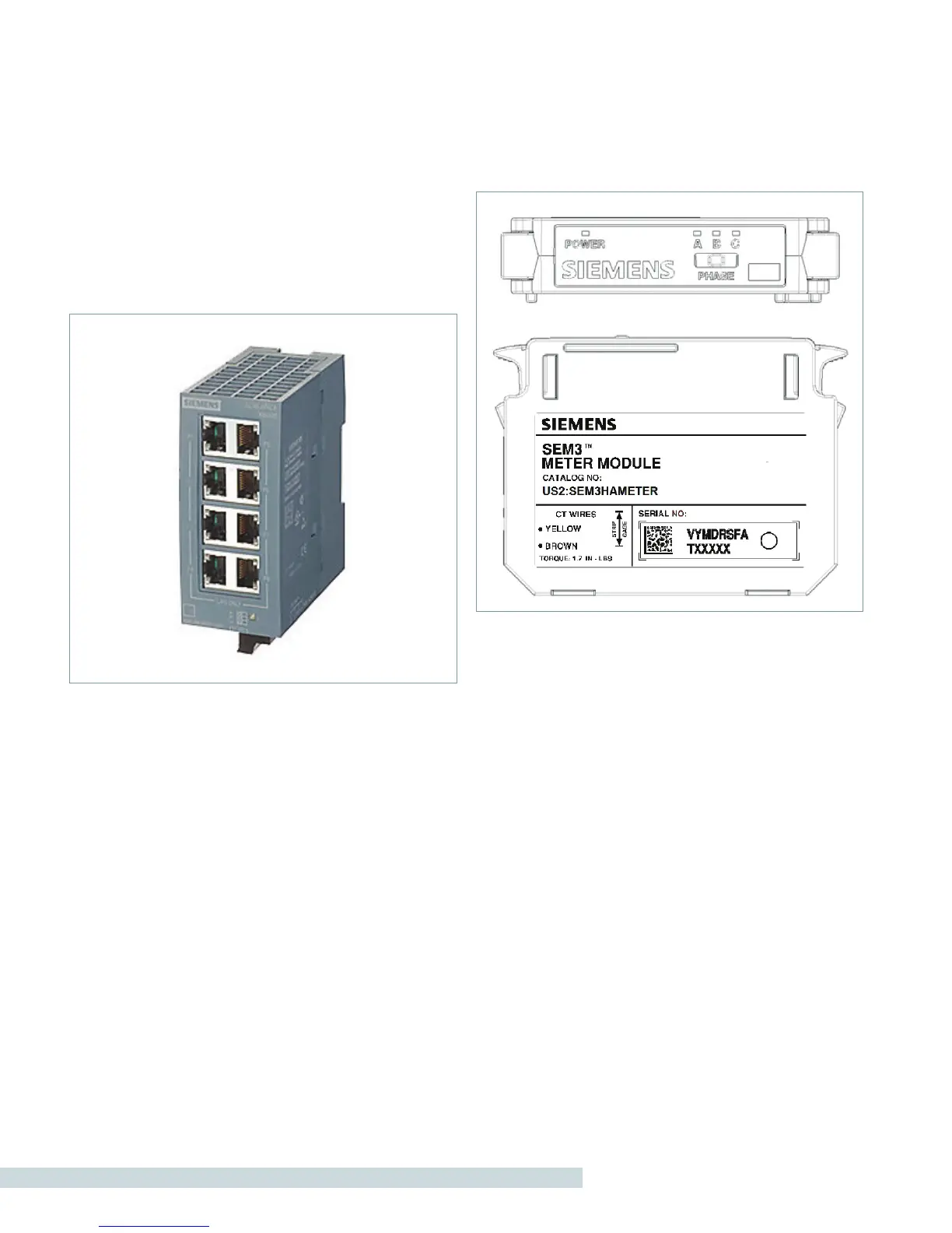
Figure 5: SIEMENS Scalence 8-Port Ethernet Switch
The output of this Ethernet switch may then be routed back to a
centralized building management system via CAT6 cable. Details
on this and other network topologies are described in Section
8.0.
6.4 OTHER SEM3™ COMPONENTS
1) Current Transformers (CTs) for use in the SEM3™ system
are 100 mA output and are self protecting/shorting. CTs are
factory installed in the bus plug. Any modification of factory
wiring will void the warranty. More information on Current
Transformers may be found in the SEM3™ User Manual
found at www.usa.siemens.com/SEM3
2) Meter Modules are single phase meters that collect energy
information via a SEM3™ CT. Meter modules are available
in either high (0.2%) or low accuracy (1%) versions. The
meter module snaps into a SEM3™ rack assembly, producing
an audible click when locked into position. The Meter Rack
provides a hard coded address for each meter module. Two
and three phase circuits require meter modules to be installed
contiguously in the rack. Gaps between modules prevent
multi-pole circuit output. Each module must have the phase
6
switch on the top of the module set to the phase that the
CT is metering. Phase A, B or C (Line 1, 2 or 3 respectively).
SEM3™ bus plugs, unless field-wired, are factory configured
with meter modules installed and circuit switches pre-set.
Additionally, a meter module configuration label is provided
on the bus plug cover showing phasing & circuit information,
see Section 7.3.
Figure 6: SEM3™ Meter Module
Note: Once the meter module is placed into the meter rack
and energized, the phase position will be indicated by a
different color LED for each position. Colors are orange for phase
A (line 1), yellow for phase B (line 2), green for phase C (line 3).
LED‘S are adjacent to the phase numbers. The power indication
LED also indicates communications by flashing. CT sizing for
each meter module will be done through the controller web
page configuration.
3) Meter Racks have the addresses for the module to controller
communications hard coded into them. Three and six meter
racks are available in the SENTRON 3/6 Bus Plug. The three
and six module racks have a rotary switch to allow them
to be configured for multiple address ranges. See section 7.3
for directions on addressing the racks and modules.
4) The Controller functions as the set up interface for the
system. System settings, CT ratios, PT ratios, alarm settings,
communications settings and passwords are all set using the
web page interface of the controller. See Section 7.1 for
directions on configuring the SEM3™ controller.

 Loading...


