7.B.1. On copper-copper bus joints, place a flat washer against
the bar with a lockwasher between the flat washer and
the nut.
7.B.2. On copper-aluminum or aluminum-aluminum bus joints,
a “Belleville” spring washer is placed under the nut, with
the concave side of the spring washer against the bus
bar.
7.C. Spacers are required at certain bus joints to insure the
cross sectional area of the joint. The conditions where
these spacers are required vary with the type of bus joint.
Refer to Figure 18.
8. Torque the .50” SAE Grade No. 5 cap screws to 50-75 lb-ft.
(68-102 Nm) torque. (If special hardware is required by an
order, other torque values will be supplied with field
assembly drawings.)
9. Install insulation boots or tape joints where required per
instructions in following sections.
10. Connect ground bus. See Figure 28. Insert bar in side
wall opening to overlap the ground bus in adjacent cubicles.
11. Torque the 0.38” SAE Grade 5 cap screw used in the
ground bus to 25-40 lb-ft. (34 to 54 Nm).
Electrical Connections
24
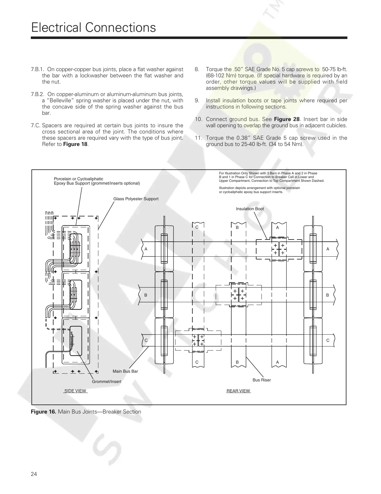
Figure 16. Main Bus Joints—Breaker Section
Insulation Boot
Bus Riser
REAR VIEW
Main Bus Bar
SIDE VIEW
A
B
C
For Illustration Only Shown with 3 Bars in Phase A and 2 in Phase
B and 1 in Phase C for Connection to Breaker Cell in Lower and
A
B
C
Upper Compartment, Connection to Top Compartment Shown Dashed.
A
B
C
Glass Polyester Support
Porcelain or Cycloaliphatic
Epoxy Bus Support (grommet/inserts optional)
Grommet/Insert
A
B
C
or cycloaliphatic epoxy bus support inserts.
Illustration depicts arrangement with optional porcelain
Courtesy of NationalSwitchgear.com
 Loading...