CI-8522 Network Interface F/O
CI-8522 Network Interface F/O - Product Information 2
C53207-A5097-C481-1C-7483 / DC8-045-2.02; Edition 11.2020
Read and understand these instructions and the relevant manual before installing,
operating, or maintaining the device. The manual is available in the download area of the
internet at https://support.industry.siemens.com.
Further Support
If special problems arise, or further information are required, please contact your Siemens
representative. The Siemens Customer Support Center provides around-the-clock support.
Disclaimer of Liability
Although we have carefully checked the contents of this publication for conformity with the
hardware and software described, we cannot guarantee complete conformity since errors
cannot be excluded.
The information provided in this manual is checked at regular intervals and any corrections
that might become necessary are included in the next releases. Any suggestions for
improvement are welcome. Subject to change without prior notice.
Copyright
Copyright © Siemens AG 2020 – All Rights Reserved
The reproduction, transmission or use of this document or its contents is not permitted
without express written authority. Offenders will be liable for damages. All rights, including
rights created by patent grant or registration of a utility model or design, are reserved.
Notes on Safety
This document contains notes that must be adhered to for your own personal safety and to
avoid damage to property. Keep it safe for later usage.
However, it does not constitute a complete description of all safety measures required for
installation, service, and maintenance of the device in question. Details are to be taken from
the device manual and those are mandatory.
Danger of severe personal injury or substantial damage to property
Hazardous voltages may occur in devices and modules during operation depending on
the design and application
. Always observe the instructions given in “Qualified
Electrical Engineering Personnel” below
.
Qualified Electrical Engineering Personnel
Qualified electrical engineering personnel may commission and operate the device
described in this document. Qualified electrical engineering personnel in the sense of this
document are people who can demonstrate up to date technical qualifications as electrical
technicians including safety and first aid training. These persons may commission, isolate,
ground and label devices, systems and circuits according to the standards of safety
engineering.
Use as Prescribed
The device may only be used for such applications as set out in the catalogs and the
technical description, and only in combination with third party equipment recommended and
approved by Siemens.
Correct and safe operation of the product requires adequate transportation, storage,
installation and mounting in a control cabinet, as well as appropriate use and maintenance.
During operation of electrical equipment, it is unavoidable that certain parts of this
equipment will carry dangerous voltages. Severe injury or damage to property can occur if
the appropriate measures are not taken:
• Before making any connections, ground the equipment and the grounding terminal.
• Hazardous voltages can be present on all switching components connected to the power
supply.
• The device does not represent a safety-oriented application.
• Even after the supply voltage has been disconnected, hazardous voltages can still be
present in the equipment (capacitor storage).
• The limit values indicated in the manual must not be exceeded; that also applies to
testing and commissioning.
Statement of Conformity
The product described conforms to the regulations of the following European
Directives
:
EMC Directive 2014/30/EU
(observance of the harmonized standard EN 60870-2-1:1996)
Low Voltage Directive 2014/35/EU
(observance of the harmonized standard EN 61010-1:2010, EN 61010-2-201:2013)
RoHS-Directive 2011/65/EU
(observance of the harmonized standard IEC/EN 63000)
Used Symbols (additional symbols are described in the manual)
Caution, risk of danger. The
documentation must be observed.
Protection class II / protective
Application
CI-8522 module is used to expand CP-8050 systems with additional Ethernet interfaces
(electrical/optical). This module can be used for communication with Ethernet devices
having electrical/optical interfaces. A maximum of two modules can be connected to a
system.
The SICAM A8000 Series is suitable for electrical distribution substations, gas distribution
substations, hydropower plants, pipelines and railway power supplies.
Unpacking a Device
• Check the package for external transport damage. A damaged packing may indicate that
the device inside is also damaged.
• Unpack the device carefully; do not use force.
• Visually check the device to ensure that it is in perfect mechanical condition.
• Return a damaged device to the manufacturer or dispose it correctly. A defective device
may neither be used nor repaired by the user.
Note: Before commissioning the device, leave it in the final operation room for at least
2
hours. This allows it to reach room temperature and to prevent dampness and
CI-8522 is shipped with 2 SFP Modules each supporting up to 2000 m
Mounting
The network interface module is designed for mounting on a DIN-rail. It must be mounted
left from the master module. Click the bus connector which is delivered with the module on
the DIN-rail and push it into the connector of the right adjacent module. Then connect the
module itself on its bus connector.
For details about the mounting refer to the respective product manual.
Commissioning
• Check the adherence of the specified limit values.
• Connect the desired type of Ethernet interfaces to the RJ45 plugs (for electrical) and SFP
LC connector (for optical).
• The module is supplied with power via the bus.
For details about the system requirements refer to the respective product
Technical Data
(from Bus)
RJ45 socket connector 8-pole (IEC 60603-7)
Auto-MDI(X)
Ethernet over fiber optic using SFP module
2 x LC duplex optical interface
Line length (MM) < 2000 m
Line length (SM) < 30000 m
Protection type acc. IEC 60529
Protection class acc. IEC 61140
Rated impulse voltage 2 kV (Category II / AC 230 V)
(Based on installation, Category II / AC 230 V &
Climatic ambient conditions
Operation temperature - 25 to + 70 °C
Temperature gradient
≤
5 to 95 % (condensation not permissible)
70 to 106 kPa (up to 3000 m)
Temperature for storage/transport
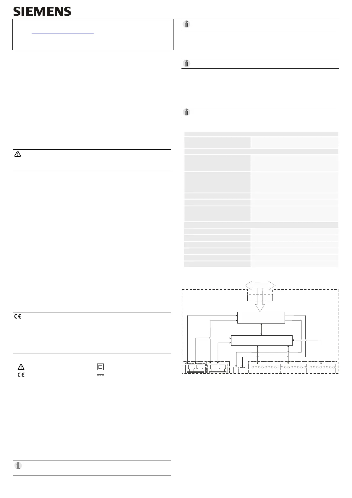
Block Diagram and Circuitry
CI-8522
BUS
FPGA
Switch
RY
ER
X5
(SFP)
X4
(SFP)
X3
(Ethernet)
X2
(Ethernet)
X1
(Ethernet)
TX RX
n
.c
.
n
.
c
.
R
X
D
-
n
.c
.
n
.c
.
R
X
D
+
T
X
D
-
T
X
D
+
X99
8
7
6
5
4
3
2
1
8
7
6
5
4
3
2
1
8
7
6
5
4
3
2
1
TX RX
n
.c
.
n
.c
.
R
X
D
-
n
.c
.
n
.
c
.
R
X
D
+
T
X
D
-
T
X
D
+
n
.c
.
n
.c
.
R
X
D
-
n
.c
.
n
.c
.
R
X
D
+
T
X
D
-
T
X
D
+
Control Signals
Control Signals
Reinforced
Insulation
Reinforced
Insulation
 Loading...