8 Transponders and loop elements
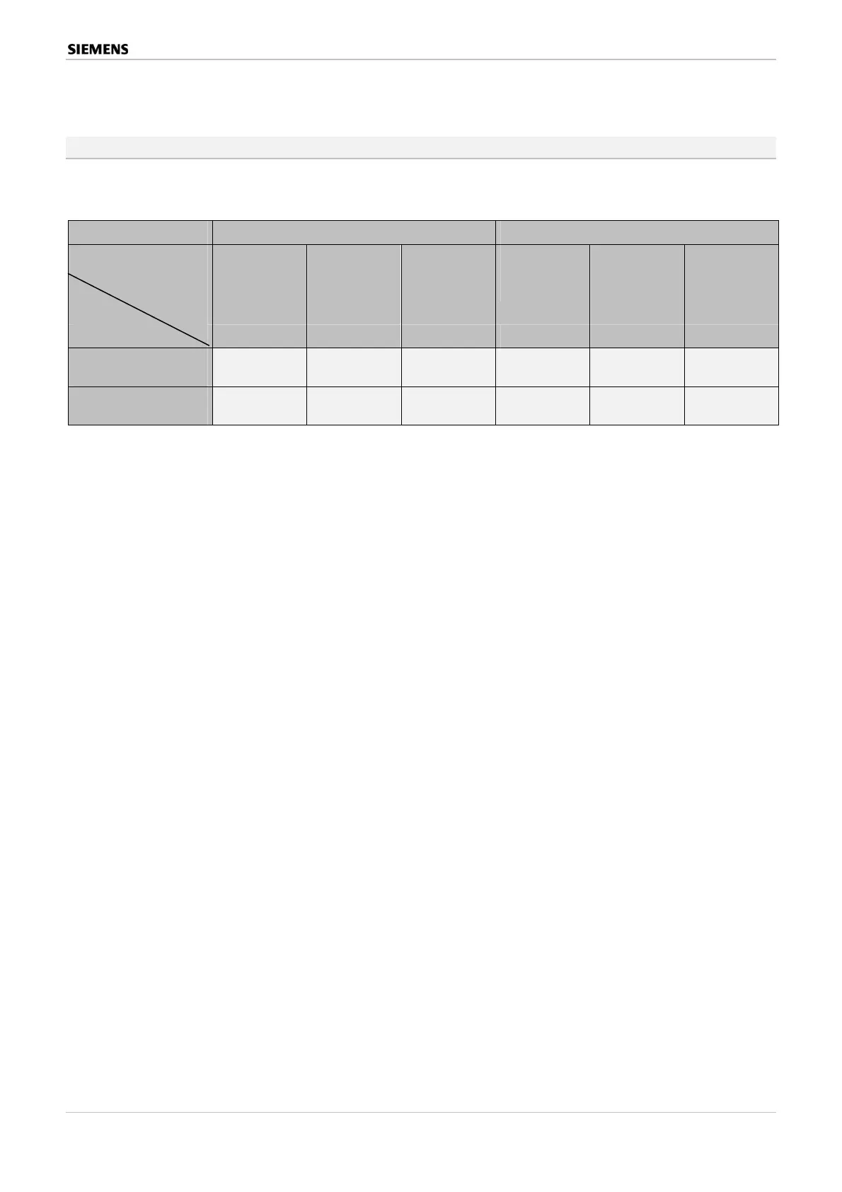
8.5 Cycle time for signals from transponders and contact couplers
Different operating conditions (polling cycles) can be selected for contacts connected via con-
tact couplers or minitransponders.
Loop cycle time 0,25 sec 1 sec – Zyklus
Multifunctional Danger Control and Indicating Panels SIGMASYS C and M (M-Modules) 53 / 128
Best.Nr. A24205-A337-B970 – Edition 12 (03/07)
Op. cond
Coupler
1-stage-poll
(for fault-free
environments)
2-stage-poll
(for fault-free
environments)
3-stage-poll
(for fault-free
environments)
1-stage-poll
(for fault-free
environments)
2-stage-poll
(for fault-free
environments)
3-stage-poll
(for fault-free
environments)
C / S *) C / S *) C / S *) C / S *) C / S *) C / S *)
Contact coupler
SPF 5300
1,7 / 2,0 sec 1,9 / 2,2 sec 2,2 / 3,2 sec 3,2 / 4,2 sec 4,2 / 5,2 sec 1,4 / 1,7 sec
0,2 / 0,7 sec 0,2 / 1,0 sec 0,2 / 1,3 sec 0,2 / 2,2 sec 0,2 / 3,2 sec 0,2 / 4,2 sec
Minitransponder
SPI 3400 (BMT & IMT)
Table 21: Cycle time for signals from transponders and contact couplers
*) C = contact actuation time Uninterrupted time for which the contact must be closed.
S = system response time Delay until the signal is displayed or the first control is tripped
(from start of contact actuation).
In general, the basic setting in SIGMAPLAN is “3-stage poll”.
 Loading...