C7-Ein-/Ausgabebaugruppe / C7 Input/Output Module
8
Produktinformation
/ Product Information
C79000-Z7074-C630-01
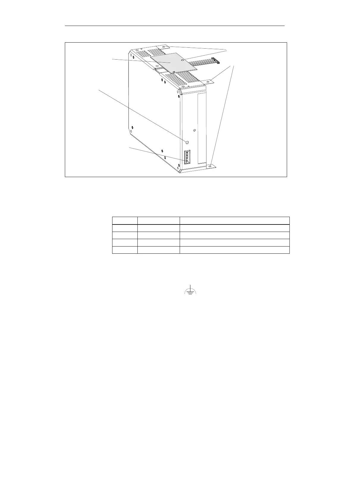
X30
DC 24V-Stromversorgung
(Gehäusebeschriftung:
”Input 24V DC 2.4A”)
Funktionserde
Bohrungen zum
Verschrauben
mit dem C7-Gehäuse
Kabelabdeckung
Bild 1-2 Ansicht der C7-Ein-/Ausgabebaugruppe mit Stromversorgung
Die
Stiftleiste ”DC 24V
-Stromversorgung” der C7-Ein-/Ausgabebaugruppe ist wie
folgt belegt:
Pin-Nr. Beschriftung Belegung
1 L+ Versorgungsspannung 24 V
2 M Masse der Versorgungsspannung 24 V
3 A+ keine Funktion
4 AE keine Funktion
Hinweis:
L+ und M sind paarweise durch einen Ferrit mit einer Windung zu installieren.
Typ: RFC-10 der Fa. KE KITAGAWA GmbH, 63110 Rodgau
Verbinden Sie die Funktionserde (siehe Bild 1-2) unter Verwendung eines
Kabelschuhs und einer Leitung, deren Querschnitt mindestens 4 mm
2
beträgt, mit
der Schrankmasse.
DC
24V
-Strom-
versorgung
Funktionserde