Pin Name Type Meaning
8 N.C.- - Not assigned
9 P5HW V 5V power supply
10 N.C. - Not assigned
11 M V Ground
12 N.C. - Not assigned
13 N.C. - Not assigned
14 N.C. - Not assigned
15 N.C. - Not assigned
Status LEDs
Table 4-15 Meaning of the status LEDs
No. Color Meaning
H1 Green Power OK
H2 Green PROFINET LED (BUS SYNC)
H3 Red PROFINET LED (BUS FAULT)
DIP switch S1
Setting the handwheel signal type
- S1 open: TTL
- S1 closed: Differential interface
Switch S2
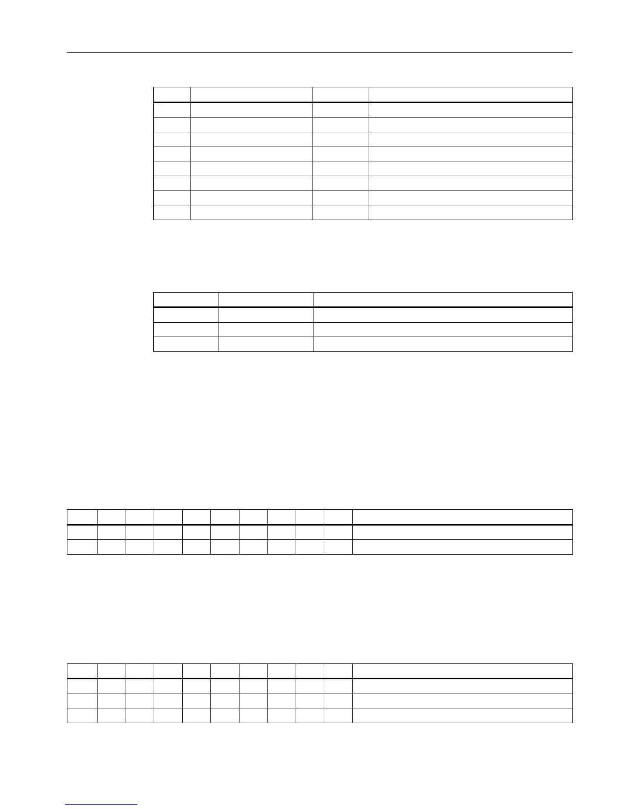
Table 4-16 Switch S2 setting as delivered
1 2 3 4 5 6 7 8 9 10 Meaning
off off
off off off off off off on on MCP address 192
The two switches S2-9 and S2-10 must remain OFF.
The switches S2-1 to S2-8 define the MCP address in the range of 0 to 255.
The addresses from 192 to 223 count as the default range.
The MCP address is used as a reference for addressing an MCP during PLC parameter
assignment.
Table 4-17 Settings of switch S2
1 2 3 4 5 6 7 8 9 10 Meaning
off off
on on on on on on on on MCP address 255
x x x x x x x x "
Interfaces
4.3 Machine control panels
ERGOline Stage 3
Manual, 02/2015, 6FC5397-4FP40-0BA0 31

 Loading...


