SIMATIC Industrial Flat Panels V2 1500/1900 4:3/5:4
A5E50653860-AA, 01/2021
15
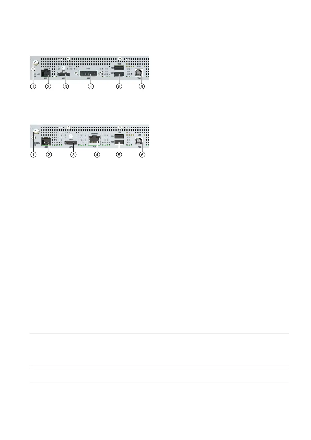
Interfaces
Standard versions
Connection for functional ground
X80 connector for 24 V DC power supply
X70 DisplayPort interface
Extended versions
Connection for functional ground
X71 Ext link interface to the Transceiver Unit
X80 connector for 24 V DC power supply
X70 DisplayPort interface
Accessories and scope of delivery
See underlying operating instructions on the electronics.
Safety instructions and further information
The general safety instructions in the underlying operating instructions apply, see section "Valid scope (Page 13)".
Mounting and connecting the device
Permitted mounting positions
The same mounting positions and ambient temperatures that are specified in the underlying operating instructions on the
electronics apply to the device.
Mounting the device
Installation guidelines
Observe all the information on safety and the degree of protection, the installation location and installation specified in the
underlying operating instructions on the front.
Preparing the mounting cutout
Note
Stability of the mounting cutout
The material in the area of the mounting cutout must be sturdy enough to ensure permanent safe mounting of the device.
To achieve the degrees of protection described below, it must be ensured that deformation of the materia
l cannot occur due
to the force of the mounting clips or operation of the device.
Note
Read the information in the section "Notes on installation" in the operating instructions of the standard device.

 Loading...


