Vor Einbau und Inbetriebnahme – Before mounting and commissioning
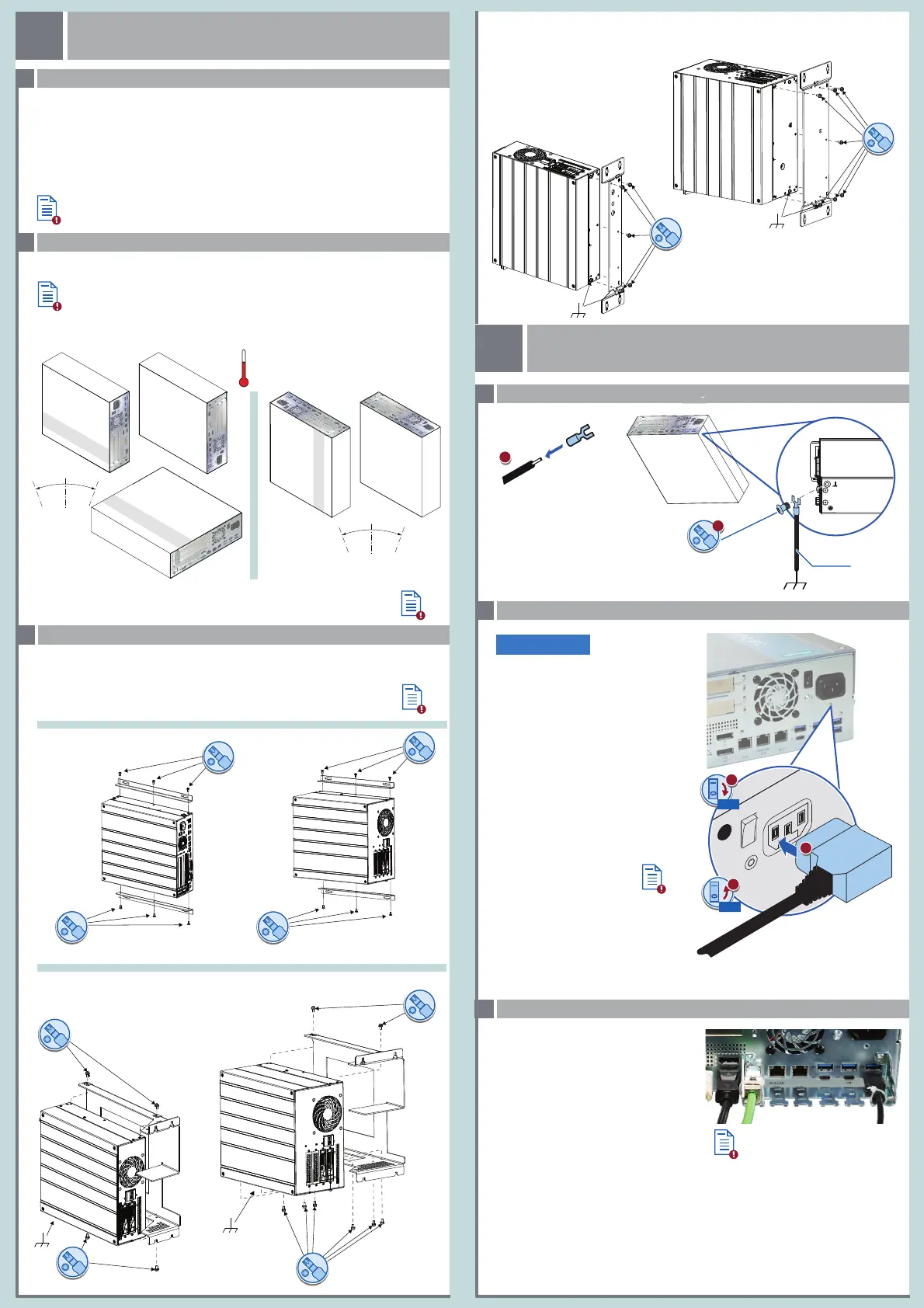
Gerät anbauen – Mounting the device
Stromversorgung anschließen – Connecting the power supply
Potentialausgleich anschließen – Connecting equipotential bonding
Zulässige Einbaulagen – Valid Mounting positions
1.1
1.2
1.3
2.2
2.1
100-240 VAC
Das Gerät ist für den Betrieb an
geerdeten Stromversorgungsnetzen
vorgesehen (TN-Netze nach VDE 0100
Teil 100 bzw.
IEC 60364-1). Der Betrieb über nicht
geerdete oder über Impedanz geerdete
Netze (IT-Netze) ist nicht erlaubt.
The device is intended for operation on
grounded power supply systems (TN
systems according to VDE 0100, Part 100,
or IEC 60364-1). It is not designed for
operation on ungrounded or impedan-
ce-grounded power networks
(IT networks).
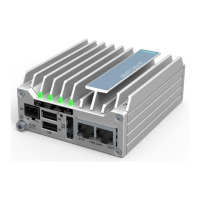
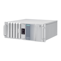
Gerät einbauen
Mounting the device
Gerät anschließen
Connecting the device
1
2
WICHTIG: Beachten Sie alle dem Gerät beiliegenden Dokumente und die Betriebsanleitung, bevor Sie
das Gerät einbauen und anschließen. Die vollständige Dokumentation des Geräts finden Sie auf dem
beiliegenden USB-Stick und im Internet
(http://www.siemens.de/simatic-ipc-doku-portal).
IMPORTANT: observe all documents enclosed with the device and the operating instructions manual
before mounting and connecting the device. You find the complete documentation of the device on
the enclosed USB-Flash drive and on the internet
(http://www.siemens.com/simatic-ipc-doku-portal).
Das Handbuchsymbol weist auf detaillierte Informationen in der Betriebsanleitung hin.
The manual symbol refers to detailed information in the operating instructions.
Stellen Sie sicher, dass die klimatischen Umgebungsbedingungen für die jeweilige Einbaulage
eingehalten werden.
Ensure that the climatic environmental conditions for the specific mounting position are
observed.
Offenes Betriebsmittel - Gehäuse erforderlich
Open Equipment - Enclosure required
2.3
Leitungen sichern – Securing the cables
Sichern Sie die angeschlossenen Leitungen zur
Zugentlastung mit Kabelbindern an den
markierten Befestigungselementen. Achten Sie
darauf, dass die Leitungen durch die Kabelbinder
nicht gequetscht werden. Beispiel:
Use cable ties to secure the connected cables to
the selected fixing elements for strain relief.
Make sure that the cables are not crushed by
the cable tie. Example:
1/ON
0/OFF
M4
₂.₅ mm²
Buchmontage (Buchmontagekit; Schnittstellen nach oben/unten)
Book mounting (vertical mounting kit; interfaces up/down)
Buchmontage (Buchmontagekit; Schnittstellen frontseitig)
Book mounting (vertical mounting kit; front interfaces)
Ensure that the mounting surface on the wall can bear four times the total weight
of the device, including fixing elements.
Use only the anchors and screws specified in the operating instructions.
Stellen Sie sicher, dass die Anschraubfläche an der Wand das Vierfache des Gesamtgewichts des
Geräts einschließlich Befestigungselemente tragen kann.
Verwenden Sie nur die in der Betriebsanleitung angegebenen Dübel und Schrauben.
T20
5 x M4
T20
7 x M4
T20
2 x M4
T20
6 x M4 T20
2 x M4
T20
2 x M4
T20
Wandmontage (Wandmontageschiene)
Wall mounting (wall monting rail)
3 x M4
T20
T20
3 x M4
3 x M4
T20
T20
3 x M4
15°
15°
20°
20°
Der Freiraum im Bereich der Lüftungsschlitze muss mindestens 100 mm betragen.
0 °C SSD (5 °C HDD)
55 °C (max. load 10 W)
Always maintain a minimum clearance of 100 mm to the area of the ventilation slots.