7
7-12
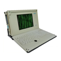
Programming Device PG 740
C79000-G7076-C742-01
The MPI/DP socket connector on the PG 740 has the following pinout:
1
5
6
9
Figure 7-4 MPI/DP Socket Connector
Pin No.
Designation Description Input/output
1 NC Pin 1 is not assigned –
2 NC Pin 2 is not assigned –
3 LTG_B Signal line B of MPI module Input/output
4 RTS_AS RTSAS, control signal for
received data stream. The
signal is “1” active when the
programmble controller is
sending.
Input
5 M5EXT M5EXT return line (GND) of
the 5 V power supply. The
current load caused by an
external user connected
between P5EXT and M5EXT
must not exceed max. 90 mA.
Output
6 P5 EXT P5EXT power supply (+5 V)
of the 5 V power supply. The
current load caused by an
external user connected
between P5EXT and M5EXT
must not exceed max. 90 mA.
Output
7 NC Pin 7 is not assigned. –
8 LTG_A Signal line A of the MPI
module.
Input/Output
9 RTS_PG RTS output signal of the MPI
module. The control signal is
“1” when the programming
device is sending.
Output
Screen On connector casing
MPI/DP Socket
Connector
Hardware Information