7
7-6
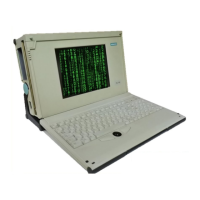
Programming Device PG 740
C79000-G7076-C742-01
Below are listed the I/O and memory assignments of a number of expansion
modules set in the factory. Please consult the relevant hardware descriptions
since you can also select other settings.
Table 7-4 I/O and Memory Assignments
I/O Address Memory Address Module HW
Interrupt
DMA
Channel
03B0 H-03DF H
0340 H-0347 H
000A 0000 H - 000C 7FFF H HIGRAPH IRQ 11*
IRQ 9
–
03E0 H-03E3 H FFFF 0000 H - FFF3 FFFF H
0000 0000 H - 000D FFFF H
CP1413
(H1)
IRQ 10* –
– 000D 0000 H - 000D FFFF H CP5410 (L2) IRQ 12* –
– 0000 0000H - 00DF FFFF H CP5412A1 IRQ 12* –
0240H-03E7H 00D0 0000H - 00DF FFFF H CP5412A2 IRQ12* –
4040 H-4061 H – DF20 IRQ 10* –
0330 H-0333 H 000D C000 H - 000D FFFF H SCSI
AHA1542
IRQ 12* DRQ 5
*) Default; you can select IRQ 10, 11, 12 or 15, depending on the module.
!
Caution
Malfunction!
You must not select IRQ 12 for the PG 740 since this interrupt is already
assigned to the trackball and/or PS/2 mouse.
I/O and Memory
Assignments
Hardware Information