2-6
SM 338 Equipment Manual
(4) J31069-D401-U1-A0-7618
Except for the restri ctions mentioned above, the measuring points can be al-
located to the sensors as de sired (e.g., 4-2-1-1, 2-2-2-2, 1-0-4-3, and so on).
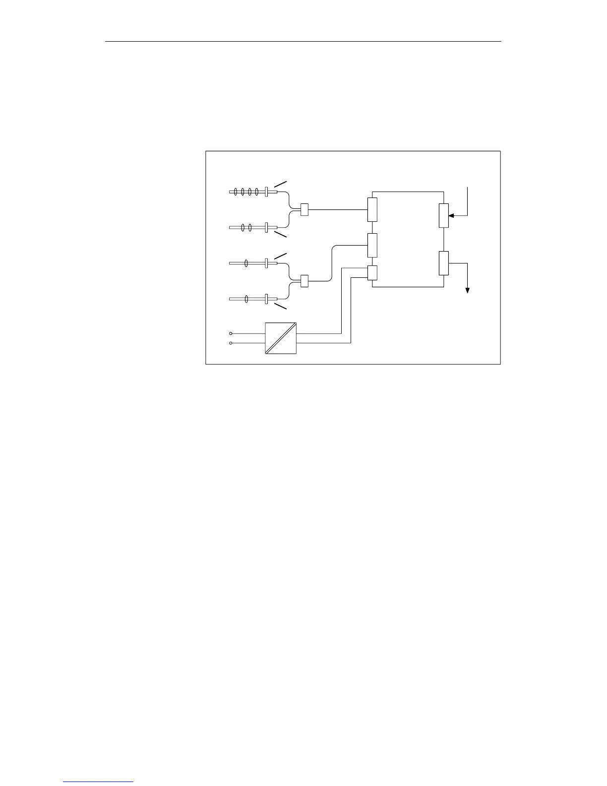
Figure 2-3 shows a complete system and a possible assignment of the mea-
suring points.
AS 300 bus
(of CPU)
AS 300 bus
(to end of rack)
Measuring
points 1 to 4
Sensor 1
Sensor 3
Sensor 2
Sensor 4
Measuring
points 5+6
Measuring
point 7
Measuring
point 8
230 V
AC
24 V
DC
X
1
X
2
SM 338
Figure 2-3 Possible assignment of the measurin g points
-
Allocation of the
measuring points
The SM

 Loading...


