4-8
SM 338 Equipment Manual
(4) J31069-D401-U1-A0-7618
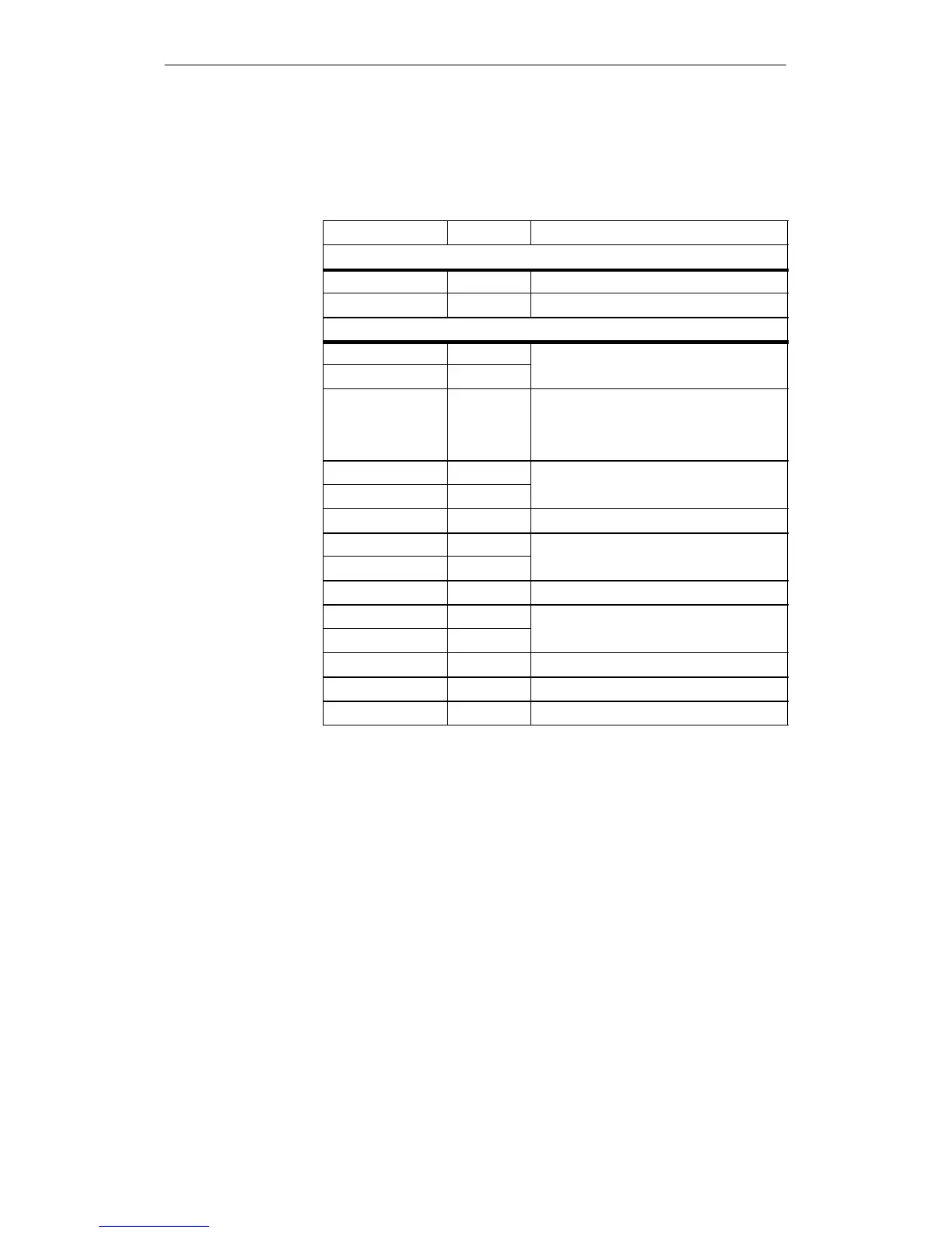
Following a new start or a RESET of the module, the parameter are a is set
with the default values specified in table 4-4.
Table 4-4 Default values for the parameter area
Value Meaning
Data record 0
Byte 0 00
H
No diagnostics and wire break monitoring
Byte 1 00
H
Alarms disabled
Data record 1
Byte 2 01
H
Sensor 1:
Byte 3 00
H
Counter 1 to measuring point 1
Byte 4 00
H
Resolution of 0.1 mm; rising edge starts/stops
counter; counter starts immediately with sent
START pulse; measuring cycle time is
16 msec.
Byte 5 02
H
Sensor 2:
Byte 6 00
H
Counter 2 to measuring point 1
Byte 7 00
H
Same as byte 4
Byte 8 03
H
Sensor 3:
Byte 9 00
H
Counter 3 to measuring point 1
Byte 10 00
H
Same as byte 4
Byte 11 04
H
Sensor 4:
Byte 12 00
H
Counter 4 to measuring point 1
Byte 13 00
H
Same as byte 4
Byte 14 00
H
Cycle time of 16 msec
Byte 15 00
H
No synchronous mode
Default settings
D

 Loading...


