Creating a Program with Function Blocks and Data Blocks
5-9
STEP 7 Getting Started
5E00171228-01
Programming Speed Monitoring
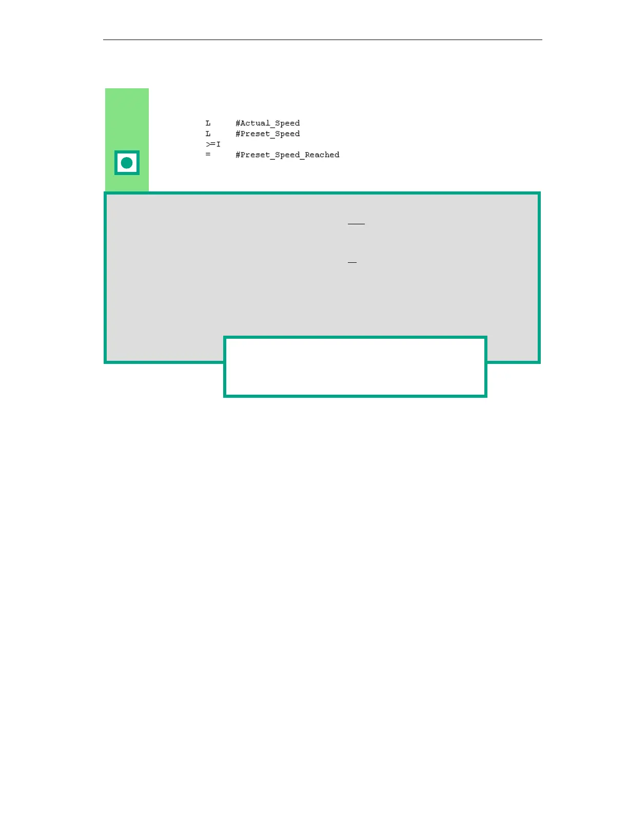
Insert a new network and enter the
corresponding instructions. Then save
your program.
When is the engine switched on and off?
When the variable #Switch_On has signal state "1" and the variable "Automatic_Mode" has
signal state "0," the engine is switched on. This function is not enabled until
"Automatic_Mode" is negated (normally closed contact).
When the variable #Switch_Off has signal state "1" or the variable #Fault has signal state
"0," the engine is switched off. This function is achieved again by negating #Fault (#Fault is
a "zero-active" signal and has the signal "1" in the normal state and "0" if a fault occurs).
How does the comparator monitor the engine speed?
The comparator compares the variables #Actual_Speed and #Setpoint_Speed and assigns
the result of the variables to #Setpoint_Speed_Reached (signal state "1").
You can find more information under Help >
Contents in the topics "Programming Blocks,"
"Creating Logic Blocks," and "Editing the Variable
Declaration" or in "Editing STL Statements."