EasyManua.ls Logo

Siemens SIMATIC STEP 7 V5.2 User Manual

Siemens SIMATIC STEP 7 V5.2
112 pages
To Next Page IconTo Next Page
To Previous Page IconTo Previous Page
Page #96 background imageLoading...
Page #96 background image
Programming a Multiple Instance
10-8
STEP 7 Getting Started
A5E00171228-01
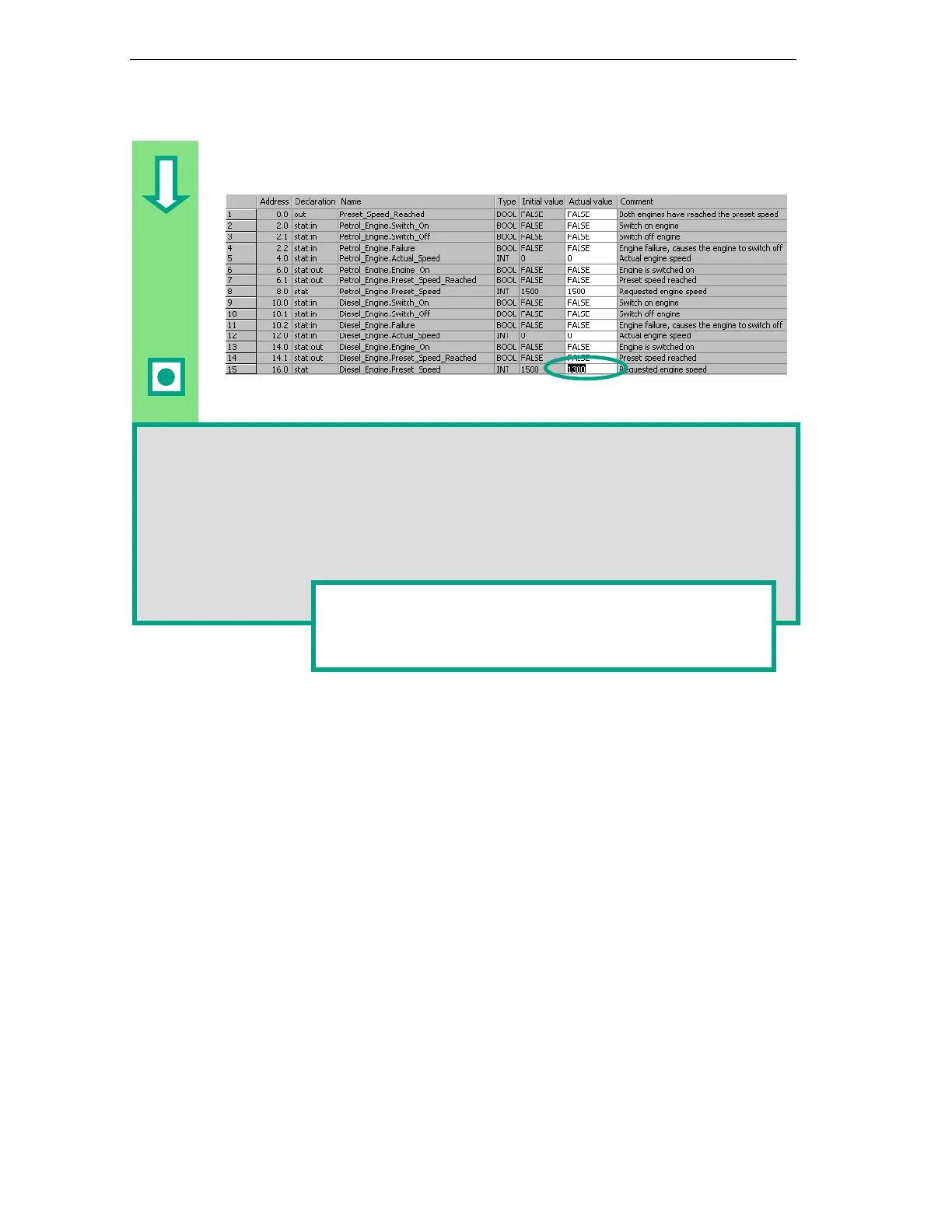
Change the actual value of the diesel engine to "1300," save the block, and then
close it.
All the variables are now contained in the variable declaration table of DB10. In the first half,
you can see the variables for calling the function block "Petrol_Engine" and in the second
half the variables for calling the function block "Diesel_Engine" (see Section 5.5).
The "internal" variables of FB1 retain their symbolic names; for example, "Switch_On." The
name of the local instance is now placed in front of these names; for example,
"Petrol_Engine.Switch_On."
You can find more information under
Help > Contents
in the
topics "Programming Blocks" and "Creating Data Blocks."
Question and Answer IconNeed help?

Do you have a question about the Siemens SIMATIC STEP 7 V5.2 and is the answer not in the manual?

Siemens SIMATIC STEP 7 V5.2 Specifications

General IconGeneral
VersionV5.2
Programming LanguagesLAD, FBD, STL, SCL, GRAPH
Operating SystemWindows
ManufacturerSiemens
PLC SupportSIMATIC S7-300, SIMATIC S7-400, SIMATIC C7
Compatible Operating SystemsWindows 2000, Windows XP

Summary

Introduction to STEP 7

What You Will Learn

Learn about programming in Ladder Logic, Statement List, or Function Block Diagram with STEP 7.

Combining Hardware and Software

Understand how to create an S7 program within a project, linking hardware and software components.

Basic Procedure Using STEP 7

Explore the two main options for creating STEP 7 projects and the overall workflow.

Installing STEP 7

Guide on installing the STEP 7 software on a programming device or PC.

The SIMATIC Manager

Starting the SIMATIC Manager and Creating a Project

Learn to start SIMATIC Manager, use the STEP 7 Wizard, and create a new project.

The Project Structure in the SIMATIC Manager and How to Call the Online Help

Understand the project structure and how to access the STEP 7 online help system.

Programming with Symbols

Absolute Addresses

Understand absolute addressing for inputs and outputs, predefined by hardware configuration.

Symbolic Programming

Learn to assign symbolic names to addresses for improved program legibility and maintainability.

Creating a Program in OB1

Opening the LAD/STL/FBD Program Window

Choose and open the programming window for Ladder Logic, Statement List, or Function Block Diagram.

Programming OB1 in Ladder Logic

Program series circuits, parallel circuits, and memory functions using Ladder Logic in OB1.

Programming OB1 in Statement List

Program AND, OR, and memory instructions using Statement List in OB1.

Programming OB1 in Function Block Diagram

Program AND, OR, and memory functions using Function Block Diagram in OB1.

Creating a Program with Function Blocks and Data Blocks

Creating and Opening Function Blocks (FB)

Learn to create and open function blocks (FBs) and understand their role in program hierarchy.

Programming FB1 in Ladder Logic

Program a function block for engine control using Ladder Logic and variable declaration.

Programming FB1 in Statement List

Program a function block for engine control using Statement List and variable declaration.

Programming FB1 in Function Block Diagram

Program a function block for engine control using Function Block Diagram and variable declaration.

Generating Instance Data Blocks and Changing Actual Values

Generate instance data blocks and learn how to change actual values for function blocks.

Programming a Block Call in Ladder Logic

Call a function block (FB1) in OB1 using Ladder Logic, connecting data blocks for engine control.

Programming a Block Call in Statement List

Call a function block (FB1) in OB1 using Statement List, connecting data blocks for engine control.

Programming a Block Call in Function Block Diagram

Call a function block (FB1) in OB1 using Function Block Diagram, connecting data blocks for engine control.

Configuring the Central Rack

Configuring Hardware

Configure the hardware for the STEP 7 project by adding modules to the rack.

Downloading and Debugging the Program

Establishing an Online Connection

Establish an online connection between the programming device and the PLC for program transfer.

Downloading the Program to the Programmable Controller

Learn the steps to download the created program to the PLC, including setting operating modes.

Testing the Program with Program Status

Test program logic by monitoring variables and observing signal changes in Ladder Logic, STL, or FBD.

Testing the Program with the Variable Table

Test program variables by monitoring and modifying their values using the Variable Table.

Evaluating the Diagnostic Buffer

Determine the cause of CPU errors or STOP states by examining the diagnostic buffer.

Programming a Function

Creating and Opening Functions (FC)

Learn to create and open Functions (FCs), understanding their role and difference from Function Blocks.

Programming Functions

Program a timer function for an engine control example using Ladder Logic, STL, or FBD.

Calling the Function in OB1

Call a programmed function (FC1) in OB1, supplying it with addresses for petrol or diesel engines.

Programming a Shared Data Block

Creating and Opening Shared Data Blocks

Learn to create and open shared data blocks (DBs) for storing data available to all blocks.

Programming a Multiple Instance

Creating and Opening a Higher-Level Function Block

Create a higher-level FB (FB10) to manage multiple instances of another FB (FB1).

Programming FB10

Program FB10 in Ladder Logic, defining variables for multiple instances of FB1.

Generating DB10 and Adapting the Actual Value

Generate a data block (DB10) for multiple instances and adapt actual values for engine control.

Calling FB10 in OB1

Call the multiple-instance FB10 in OB1, replacing individual FB1 calls.

Configuring the Distributed I/O

Configuring the Distributed I/O with PROFIBUS DP

Configure distributed I/O modules using PROFIBUS DP, connecting sensors and actuators remotely.

Appendix A

Overview of the Sample Projects for the Getting Started Manual

Lists available sample projects for the Getting Started manual, detailing their scope and programming language.

Related product manuals