Programming a Multiple Instance
10-9
STEP 7 Getting Started
5E00171228-01
10.4 Calling FB10 in OB1
The call for FB10 is made in OB1 in our example. This call represents the same
function which you have learned while programming and calling FB1 in OB1 (see
Section 5.6 onwards.). Using multiple instances, you can replace Networks 4 and
5 programmed from Section 5.6 onwards.
Open OB1 in the project in which you
have just programmed FB10.
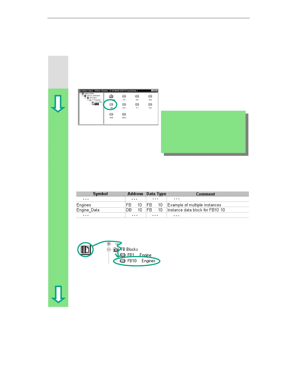
Defining Symbolic Names
The LAD/STL/FBD program window is open. Open the symbol table using the
menu command Options > Symbol Table and enter the symbolic names for the
function block FB10 and the data block DB10 in the symbol table.
Then save the symbol table and close the window.
Programming the Call in Ladder Logic
Insert a new network at the end of OB1
and add the call for FB10 ("Engines").
If you copied the symbol table from a sample
project (ZEn01_01_STEP7__STL_1-10,
ZEn01_05_STEP7__LAD_1-10 or
ZEn01_03_STEP7__FBD_1-10) to your
"Getting Started" project in Chapter 4, you do
not need to add any symbols now.