Interrupts/diagnostics alarms
5.1 Status and error displays
I/O device digital inputs DI 16x24VDC M12-L 8xM12 (6ES7141-6BH00-0BB0)
24 Equipment Manual, 06/2021, A5E46570510-AB
Meaning of the LEDs
The following tables set out the meaning of the status and error displays. Measures for
dealing with diagnostics alarms can be found in the section Diagnostics alarms (Page 27).
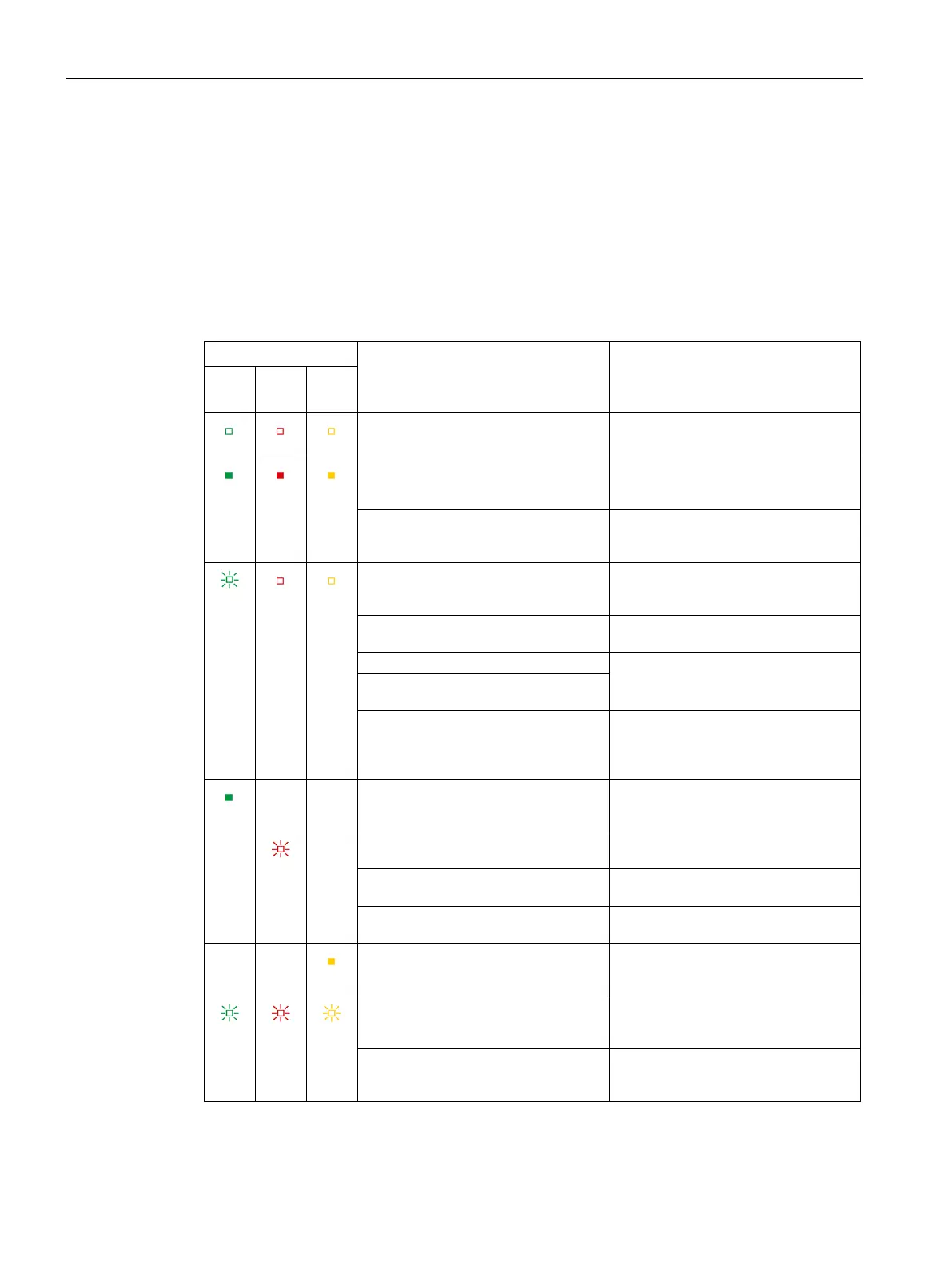
Behavior of the LEDs RN/NS (RUN/network status), ER/MS (ERROR/module status) and MT/IO
(MAINT/IO status) on PROFINET
Table 5- 1 Fault display of the LEDs
Meaning Solution
RN/
ER/
MT/
Missing or insufficient supply voltage
at the I/O device.
Check the supply voltage.
On
On
On
Test of LEDs during startup: The three
LEDs light up simultaneously for ap-
The three LEDs light up simultaneous-
ly for approximately 2 s while "Reset
to factory settings" is running.
Flash-
ing
Off
Off
The ET 200eco PN is disabled.
Activate the ET 200eco PN with the
configuration software or via the user
The ET 200eco PN is not or incorrectly
configured.
Configure the ET 200eco PN via the
configuration software.
The ET 200eco PN is starting up.
The ET 200eco PN is being assigned
Loading firmware (when the firm-
ware update is performed during
startup, all LEDs retain their current
On
Not
rele-
Not
rele-
The ET 200eco PN is currently ex-
changing data with the IO controller.
Not
rele-
vant
Flash-
ing
Not
rele-
vant
Module diagnostics is available Evaluate the diagnostics and elimi-
The preset configuration does not
match the actual configuration.
Check the configuration of the ET
200eco PN.
Correct the errors in the parameter
assignment.
rele-
rele-
On
Evaluate the maintenance events.
Flash-
ing
Flash-
ing
Flash-
ing
The "Node flash test" is running (the
P1 LK and P2 LK LEDs of the PROFINET
interface are also flashing).
Hardware or firmware defective (The
P1 LK and P2 LK LEDs of the PROFINET
interface are not flashing).
Replace the ET 200eco PN module.
 Loading...


