Mounting, wiring, connecting, system interfaces, configuration guidelines
12.2 Wiring, connecting
SIMOCODE pro
212 System Manual, 05/2019, A5E40507475002A/RS-AD/004
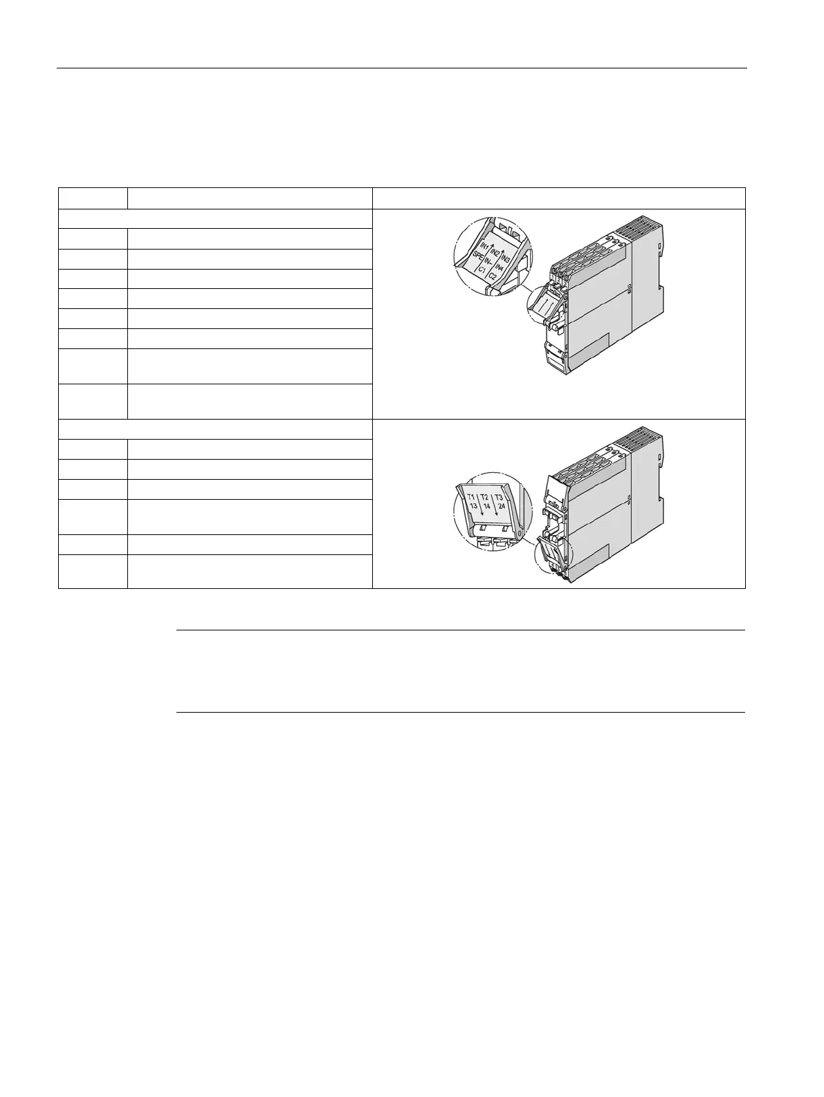
Terminal assignment of the multifunction module
Table 12- 13 Assignment of the removable terminals, multifunction module
IN1 Digital input IN1
1)
C1 Terminal 1, 3UL23 residual current
C2 Terminal 2, 3UL23 residual current
Input T1, temperature sensor
Input T2, temperature sensor
Input T3, temperature sensor
13 Common potential for relay outputs 1
24 Relay output OUT2
1)
pro via terminal SPE with the maximum possible cross-section and
with as short a cable as possible to t
he functional ground of the control cabinet, e.g. to the
grounded mounting plate of the control cabinet.