Mounting, wiring, connecting, system interfaces, configuration guidelines
12.2 Wiring, connecting
SIMOCODE pro
System Manual, 05/2019, A5E40507475002A/RS-AD/004
215
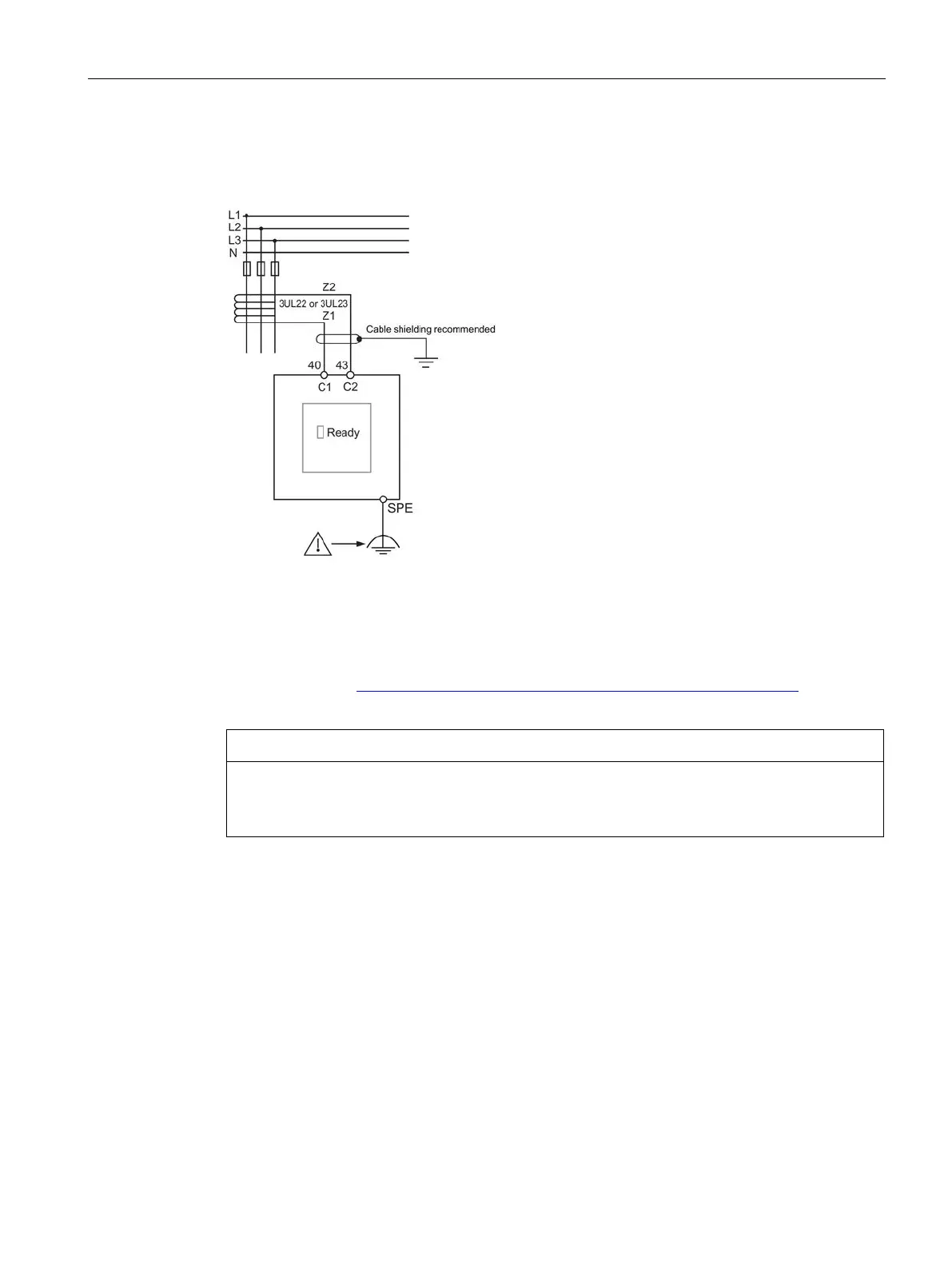
Ground-fault module connection example
Figure 12-22 Ground-fault module connection example
The output signal of the transformers 3UL22/3UL23 is connected to terminals C1 and C2 of
the corresponding ground-fault module.
Information on installing the residual current transformer 3UL23: See Manual 3UG4/3RR2
Monitoring Relay (https://support.industry.siemens.com/cs/ww/en/view/54397927
),
Chapter 13.2.5.
Routing the connecting cables / using shielded cables
To avoid interference injection, which could result in incorrect measurements, route these
connecting lines parallel and twisted, if possible, or use shielded cables.