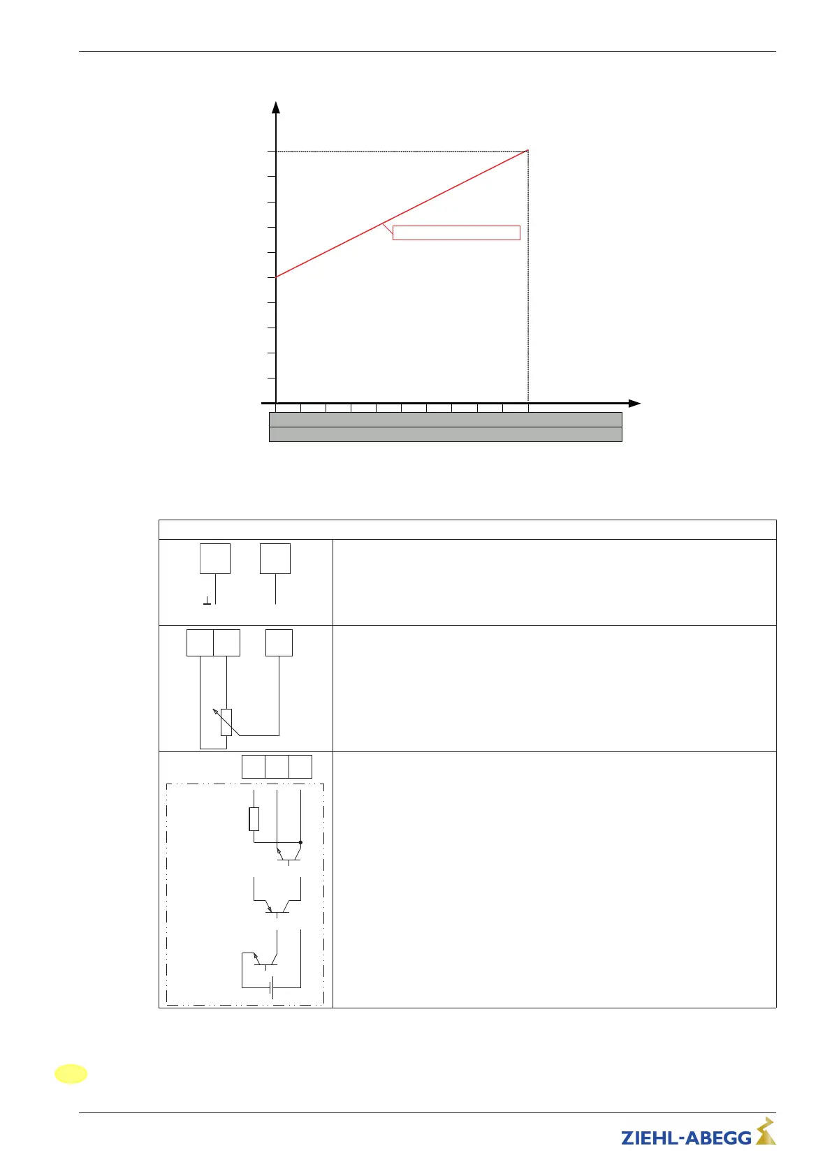
Diagram for setting via external signal.
nM
28.04.2015
v_ecblue_100_set_min50_max100.vsd
1 2
3
4 5
6 7 8
9
10
Analog In 1
80
70
60
50
40
30
20
10
0...10 V
10 20
30
40 50
60 70 80 90
100
0...100 % PWM
0
0
90
100 %
n-min = 50 % n-max. = 100 %
nM Motor speed
100 % Rated speed
Si Speed setting signal 0...10 V / 0...100 % PWM
Possibilities for speed setting
•
Control via external setting signal 0...10 V.
•
By external wiring with a resistor (499 Ω / 0,25 W) between the terminals “E1”
and “GND” parallel to the input signal, activation with a 0...20 mA signal is
possible.
•
Speed setting by 10 kΩ potentiometer at terminals “+10 V” and “GND” pick-
off at terminals “E1”.
10V GND E1
Signal PWM
f = 1...10 kHz
10 kΩ
10 V
GND
E1
E1
GND
15...28 V
+
-
10 V
E1
•
Control via external setting signal PWM.
Assembly instructions ECblue Electrical installation
L-BAL-F065-GB 1617 Index 004 Part.-No. 00702801-GB
18/28
182